3 - 1
Section E
Hydraulics
9803/6410
Section E
3 - 1
Issue 1
Schematics
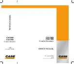
Schematic, Hydraulic Circuit JS130
1
MOTOR; SLEW
2
RAM; DIPPER
3
VALVE; ASSEMBLY
4
MOTOR; TRACTION
5
ROTARY COUPLING
6
RAM; BUCKET
7
RAM; BOOM (L)
8
RAM; BOOM (R)
9
VALVE; SHUTTLE
10
VALVE; CONTROL
11
VALVE; SOLENOID
12
ORIFICE
13
FILTER; LINE
14
VALVE; CHECK
15
VALVE; CHECK
16
RADIATOR
17
RADIATOR
18
BREATHER; AIR
19
TANK; SUMP
20
FILTER; LINE
21
STRAINER
22
VALVE; RELIEF
23
FILTER; RETURN
24
VALVE; STOP
25
NEPHRON FILTER
26
VALVE; STOP
27
VALVE; CHECK
28
SWITCH; PRESS.
29
VALVE; SOLENOID
30
VALVE; SHUTTLE
31
ACCUMULATOR
32
VALVE; CHECK
33
FILTER; LINE
34
PUMP; HYD
35
VALVE; REMOTE CONT
36
VALVE; REMOTE CONT
37
VALVE; SHUTTLE
38
SWITCH; PRESS
39
VALVE; STOP
40
CUSHION VALVE
41
SWITCH PRESS.
42
VALVE; STOP
43
VALVE; SPL
44
VALVE; RELIEF
45
FILTER; LINE
Summary of Contents for JS130
Page 65: ...Section 3 Section 3 9803 6410 Issue 1 9 1 9 1 Routine Maintenance Component Location Diagram...
Page 118: ......
Page 119: ...3 1 Section C Electrics 9803 6410 Section C 3 1 Issue 1 Layout Operator s Cab...
Page 142: ...5 3 Section C Electrics 9803 6410 Section C 5 3 Issue 1 Pump Control FLOW CHART...
Page 207: ......
Page 209: ......
Page 210: ...3 4 Section E Hydraulics 9803 6410 Section E 3 4 Issue 2 Schematics Shuttle Block...
Page 532: ...Contents Page No Technical Data 1 1 i Engine 9803 6410 i Issue 1 Section K Section K...