MAINTENANCE AND SERVICE
All wiring connections should be inspected and cleaned or remade periodically.
The frequency of maintenance depends on the metals involved in the connec-
tions, atmospheric conditions and other factors, but once per year is the minimum.
In the event that your system ever needs service, contact your local JBL dealer
or distributor, or visit www.jbl.com for a service center near you.
Vertically Stand-Mounting the
Receiver Module
Step 1
.
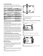
Remove the corner screws located on the left side of the receiver module
when viewed from the bottom, looking at the front, as shown in Figure 8.
Figure 8.
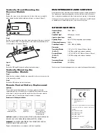
Step 2.
Rest the receiver module on top of the stand and reattach the two screws that
were removed in Step 1 through the holes in the stand into the bottom of the
receiver module, as shown in Figure 9.
Figure 9.
Step 3.
Rotate the JBL logo 90˚ by gently pulling it out and turning it.
Vertically Mounting the
Transmitter Module
Step 1.
Attach the four included self-adhesive rubber feet in the recesses on the side
of the transmitter module.
Step 2.
Rotate the JBL logo to a vertical orientation.
Remote Control Battery Replacement
CAUTION:
When replacing the lithium battery in the remote, make sure that the
replacement battery is inserted in correct polarity. Place the battery so that
its positive (+) side faces up with the tray held so that the surface with the
dot and/or with a (+) mark next to the part number is facing up.
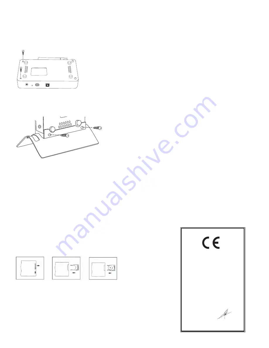
Remote control battery installation
CAUTION:
DANGER OF EXPLOSION IF BATTERY IS INCORRECTLY REPLACED.
REPLACE ONLY WITH THE SAME OR EQUIVALENT TYPE (CR2025).
WARNING:
DO NOT EXPOSE BATTERIES TO EXCESSIVE HEAT SUCH AS
DIRECT SUNLIGHT, FIRE OR THE LIKE.
Dispose of dead batteries in accordance with local regulations.
Push small tab
toward battery slot.
Pull battery
drawer out.
Insert new battery
with “+” side up, and
slide battery drawer
back into remote.
Declaration of Conformity
We, Harman Consumer Group, Inc.
2, route de Tours
72500 Château du Loir
France
declare in own responsibility that the product described
in this owner’s manual is in compliance with technical
standards:
EN 55013:2001+A1:2003
EN 55020:2002+A1:2003
EN 61000-3-2:2000
EN 61000-3-3:1995+A1:2001
EN 60065:2002
Laurent Rault
Harman Consumer Group, Inc.
Château du Loir, France 10/08
SPECIFICATIONS
Frequency Range:
20Hz – 20kHz
(+0dB, –1dB)
Amplifier Output:
50 Watts per channel
Signal-to-Noise Ratio:
80dBA
Operating Range:
Up to 70' (22m), depending upon conditions
RF Operating Frequency:
2.4GHz
Power Requirement:
100V – 240V AC, 50/60Hz
Dimensions
Transmitter Module:
1-1/8" x 6" x 3-7/8" (29mm x 154mm x 98mm)
(H x W x D)
3-3/4" (95mm) high with antenna extended
Receiver Module:
1-1/8" x 6-3/16" x 4-5/8" (29mm x 158mm x 116mm)
(H x W x D)
3-3/4" (95mm) high with antenna extended
Weight
Transmitter Module:
0.6 lb (0.3kg)
Receiver Module:
0.9 lb (0.4kg)
Features, specifications and appearance are subject to change without notice.
JBLP2744-WEM1-OM.qxd 10/29/08 2:42 PM Page 7


