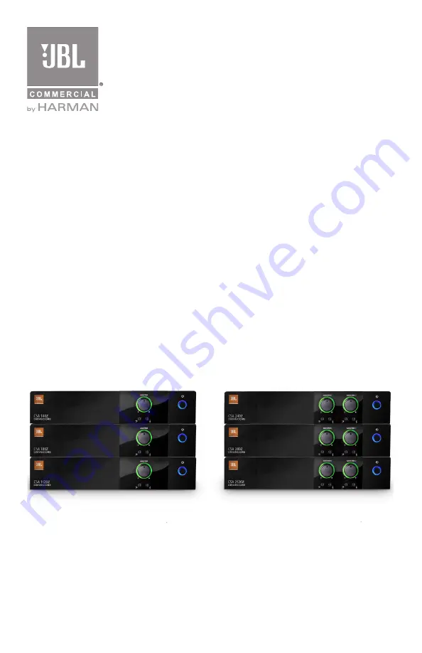
CSA 140Z
CSA 180Z
CSA 1120Z
CSA 240Z
CSA 280Z
CSA 2120Z
Commercial Series Amplifier
Operation Manual
JBL Commercial Series
Page 1: ...CSA 140Z CSA 180Z CSA 1120Z CSA 240Z CSA 280Z CSA 2120Z Commercial Series Amplifier Operation Manual JBL Commercial Series...
Page 2: ...8760 South Sandy Parkway Sandy UT All Rights Reserved Contents Important Safety Instructions 3 JBL DECLARATION OF CONFORMITY 5 1 0 Welcome 7 1 1 Features 7 1 2 Front Control Panels and Indicators 8 1...
Page 3: ...Connect this equipment only to the power source indicated on the equipment rear panel To reduce the risk of fire or electric shock refer servicing to qualified service personnel or equivalent If conne...
Page 4: ...ix it with gen eral household waste There is a separate collection system for used electronic products in accordance with legislation that requires proper treatment recovery and recycling Private hous...
Page 5: ...08 Limitation of Voltage Fluctuations and Flicker in Low Voltage Supply systems Rated Current less than or equal to 16A EN 55022 2010 Limits and Methods of Measurement of Radio Disturbance Characteris...
Page 6: ...6...
Page 7: ...e 1 1 Features 1 or 2 channel outputs Integrated Output Transformer to drive 70V or 100V speaker systems Ideal for commercial and industrial use System may be expanded by adding JBL Commercial Series...
Page 8: ...g i e the signal has reached the threshold of audible distortion D Tone Controls Bass and Treble potentiometers on each output channel E Illuminated ring around the power switch Green indicates that t...
Page 9: ...put Connector Stereo unbalanced sources will be summed together Ch2 4 E Audio Input Connector 3 pin Euro block connector balanced input Ch2 4 F Sleep Disable Switch Disables the Sleep mode if you don...
Page 10: ...NING Before you start to set up your amplifier make sure you read and observe the Important Safety Instructions found at the beginning of this manual 2 2 Installing Your Amplifier CAUTION Before you b...
Page 11: ...1 Figure 2 2 1 Dimensions Figure 2 2 2 Mounting Kit long angle bracket flat bracket front angle bracket rear angle brackets rear flat brackets 218 44 mm 8 6 in 303 4 mm 11 9 in 43 3 mm 1 7 in CSA 1120...
Page 12: ...of the rear of the amplifier assembly with the screws provided 5 Install the assembly into the cabinet using the rack mount screws through the front angle brackets For details of installation in the...
Page 13: ...angle bracket to the other side at the front of the amplifier using the screws provided 2 Attach one of the front angle brackets to the other side of the assembly as shown in the diagram with the scr...
Page 14: ...les to connect the amplifier balanced input by using the included Euro block connectors see Figure 2 4 Unbalanced lines may be used but may result in hum or RF noise very long cable runs You can also...
Page 15: ...wires should be twisted cable if possible To prevent the possibility of short circuits the wires should be stripped back no greater than 6 mm 1 4 inch see Figure 2 5 Suggested below are guidelines to...
Page 16: ...nel can drive is 4 Ohms Therefore you can connect up to four 16 Ohm speakers two 8 Ohm speakers or one 4 Ohm speaker to an amplifier output channel High Impedance Speakers should be driven using the a...
Page 17: ...electrician 2 8 Protecting Your Speakers It s wise to avoid clipping the amplifier signal Not only does clipping sound bad but it can damage high frequency drivers The built in clip limiter prevents...
Page 18: ...ip LEDs constantly flashing 7 Do not overdrive the mixer which will cause clipped signal to be sent to the amplifier Such signals will be reproduced with extreme accuracy and loudspeaker damage may re...
Page 19: ...itches in a 70Hz high pass filter 3 3 Remote Volume Control Remote volume control can be implemented using a CSR V controller connected via an Ethernet cable to the RJ45 connector on the back panel Fo...
Page 20: ...ed and turned down POSSIBLE REASON The Hi Z switch is OFF while using the 70V or 100V outputs POSSIBLE REASON The power switch is OFF Note that while plugged in the amplifier will be in standby mode a...
Page 21: ...70 dB Tone Controls Bass and Treble non detented potentiometers on each channel Bass 10dB 100Hz Treble 10dB 10kHz Nominal AC Line Voltages 100 240V 50 60 Hz Minimum Load Impedance Low Z Output 70V Out...
Page 22: ...er Service your system installer or retailer On The World Wide Web www jblcommercialproducts com Professional Contacts Outside the USA Contact the JBL Professional Distributor in your area A complete...
Page 23: ...23...
Page 24: ...Part Number 5040963 Issue 01 14 JBL Commercial 8760 South Sandy Pkwy Sandy UT 84070 USA 801 566 8800...