JBL 300 Series, Manual
The Bosch 300 Series is a high-performance appliance designed to simplify your household chores. Complete with a comprehensive Use And Care Manual, this manual can be easily downloaded for free from manualshive.com. Discover the full potential of your Bosch 300 Series and keep it operating at its best.
Share
Download


Reviews:
No comments
Related manuals for 300 Series
8000 Series
Brand: KEF Pages: 13
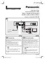
SC-HTE180
Brand: Panasonic Pages: 2
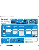
VieraLink SC-ALL30T
Brand: Panasonic Pages: 12
SC-HTB550
Brand: Panasonic Pages: 36
SC-HTB570
Brand: Panasonic Pages: 2
SC-BT205
Brand: Panasonic Pages: 2
SC-HTB20
Brand: Panasonic Pages: 2
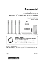
SCBT730 - BLU RAY HOME THEATER SYSTEM
Brand: Panasonic Pages: 2

SC-ALL70T
Brand: Panasonic Pages: 12
SC-HTB15
Brand: Panasonic Pages: 32
SC-HTB8
Brand: Panasonic Pages: 24
SC-HTB20
Brand: Panasonic Pages: 32
SC-HTB400
Brand: Panasonic Pages: 32
SC-BTT500W
Brand: Panasonic Pages: 52
SC-BTT270
Brand: Panasonic Pages: 52
SC-HTB880
Brand: Panasonic Pages: 2
SC-HTB770
Brand: Panasonic Pages: 44
SC-HTE80
Brand: Panasonic Pages: 36


