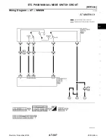

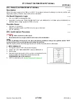
DTC P0826 MANUAL MODE SWITCH CIRCUIT
AT-589
[RE5F22A]
D
E
F
G
H
I
J
K
L
M
A
B
AT
Revision: November 2006
2006 Altima
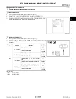
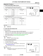
Diagnostic Procedure
ECS009I5
1.
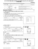
CHECK MANUAL MODE SWITCH CIRCUIT
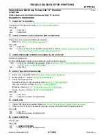
With CONSULT-II
1.
Turn ignition switch “ON”. (Do not start engine.)
2.
Select “A/T” with “DATA MONITOR” mode in CONSULT-II.
3.
Read out ON/OFF switching action of the “MANU MODE SW”,
“NON M-MODE SW”, “UP SW”, “DOWN SW”.
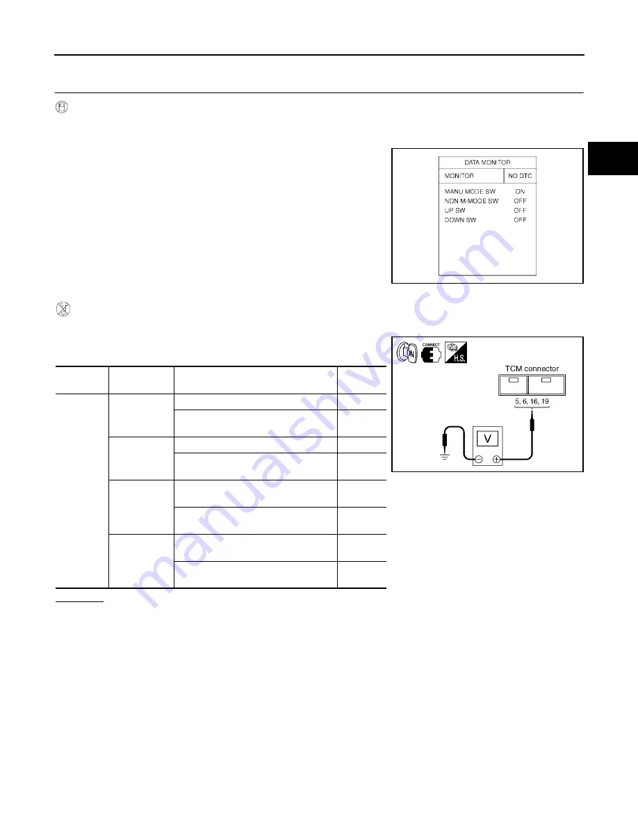
Without CONSULT-II
1.
Turn ignition switch “ON”. (Do not start engine.)
2.
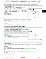
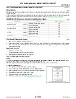
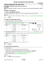
Check voltage between the TCM connector terminals and
ground.
OK or NG
OK
>> GO TO 4.
NG
>> GO TO 2.
SCIA2917E
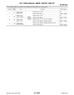
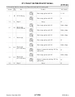
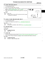
Connector
No.
Terminal
Condition
Voltage
(Approx.)
F56
5 - Ground
Selector lever: + side
0V
Other than the above
Battery
voltage
6 - Ground
Selector lever: - side
0V
Other than the above
Battery
voltage
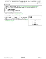
16 - Ground
Selector lever: “P”, “R”, “N” or “D” posi-
tion
0V
Selector lever: Manual shift gate posi-
tion
Battery
voltage
19 - Ground
Selector lever: Manual shift gate posi-
tion (neutral)
0V
Other than the above
Battery
voltage
SCIA2918E