AT-500
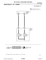
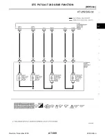
[RE5F22A]
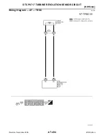
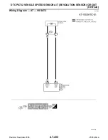
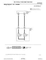
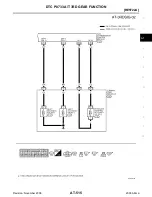
DTC P0722 VEHICLE SPEED SENSOR A/T (REVOLUTION SENSOR) CIRCUIT
Revision: November 2006
2006 Altima
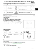
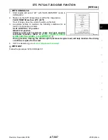
3.
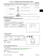
CHECK DTC
Perform “DTC Confirmation Procedure”. Refer to
AT-497, "DTC Confirmation Procedure"
.
OK or NG
OK
>> INSPECTION END
NG
>> GO TO 4.
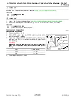
4.
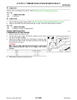
CHECK TCM
1.
Check TCM input/output signal. Refer to
AT-459, "TCM Input/Output Signal Reference Values"
2.
If NG, recheck TCM pin terminals for damage or loose connection with harness connector.
OK or NG
OK
>> INSPECTION END
NG
>> Repair or replace damaged parts.
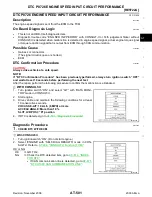
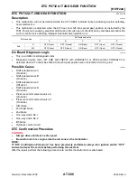
Component Inspection
ECS009EP
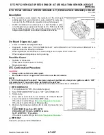
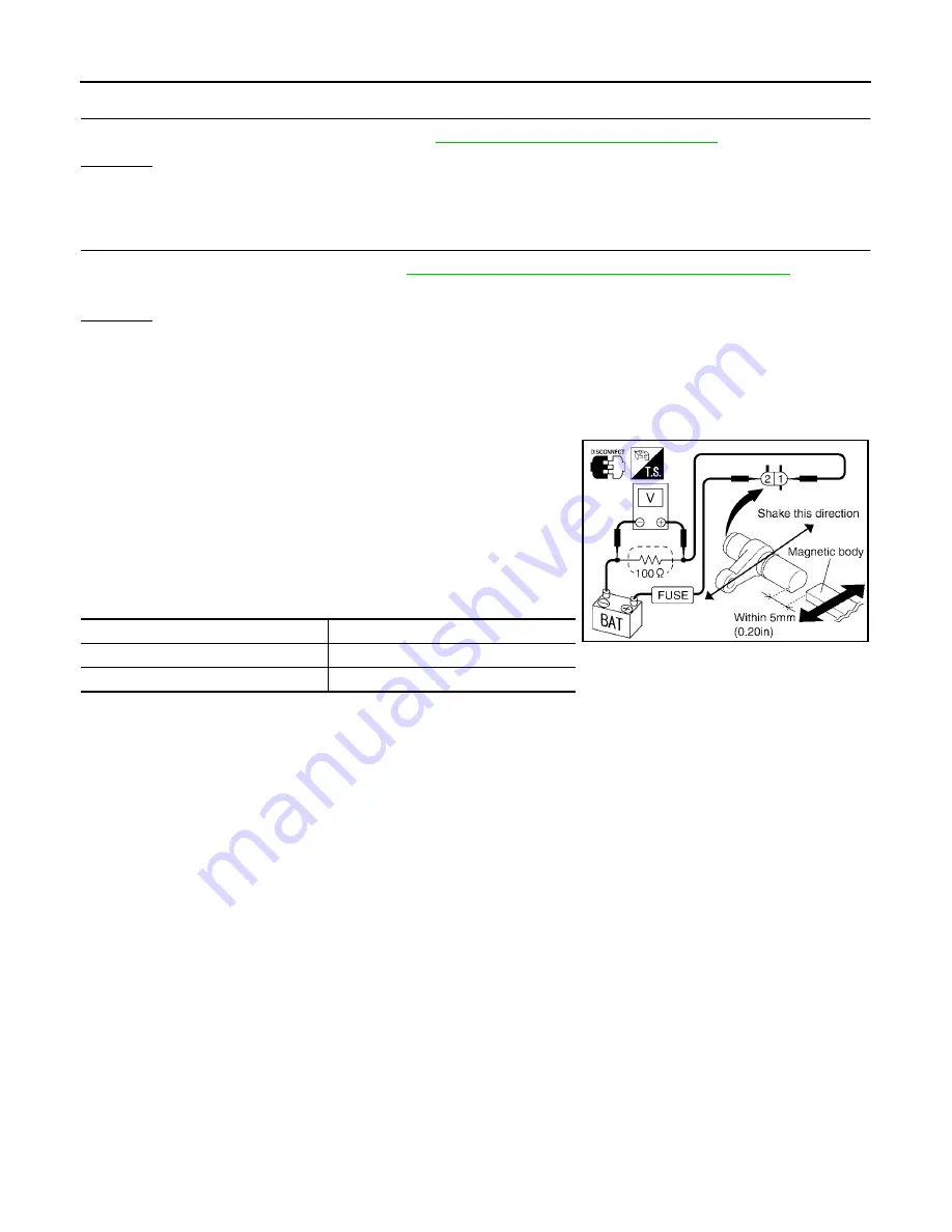
REVOLUTION SENSOR
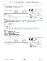
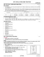
1.
Remove revolution sensor.
2.
Connect 12V power supply and 100
Ω
resistance to the termi-
nal. (Do not mistake polarity)
3.
Inspect the voltage of HIGH and LOW signal by shaking mag-
netic body from side to side at revolution sensor tip [gap is within
5mm (0.20 in)].
CAUTION:
Make sure to shake direction from bolt hole to sensor-self
when shaking magnetic body. If not, voltage value cannot
change.
4.
If NG, replace revolution sensor.
Signal
Voltage (Approx.)
HIGH
1.2 - 1.6V
LOW
0.4 - 0.8V
SCIA2927E