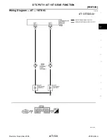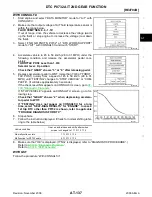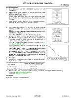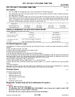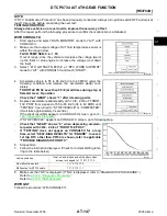
DTC P0732 A/T 2ND GEAR FUNCTION
AT-139
[RE4F04B]
D
E
F
G
H
I
J
K
L
M
A
B
AT
Revision: November 2006
2006 Altima
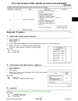
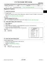
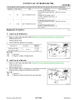
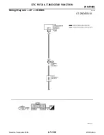
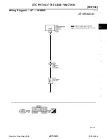
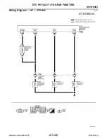
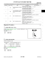
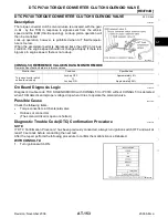
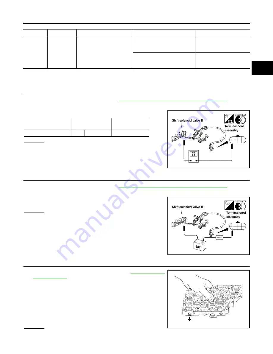
TCM TERMINALS AND REFERENCE VALUE MEASURED BETWEEN EACH TERMINAL AND 25 OR 48 (TCM GROUND)
Diagnostic Procedure
ECS0097H
1.
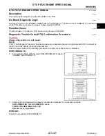
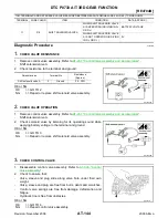
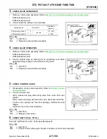
CHECK VALVE RESISTANCE
1.
Remove control valve assembly. Refer to
AT-267, "Control Valve Assembly and Accumulators"
–
Shift solenoid valve B
2.
Check resistance to the terminal and ground.
OK or NG
OK
>> GO TO 2.
NG
>> Repair or replace shift solenoid valve assembly.
2.
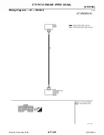
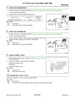
CHECK VALVE OPERATION
1.
Remove control valve assembly. Refer to
AT-267, "Control Valve Assembly and Accumulators"
–
Shift solenoid valve B
2.
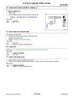
Check solenoid valve by listening for its operating sound while
applying battery voltage to the terminal and ground.
OK or NG
OK
>> GO TO 3.
NG
>> Repair or replace shift solenoid valve assembly.
3.
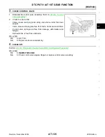
CHECK CONTROL VALVE
1.
Disassemble control valve assembly. Refer to
2.
Check to ensure that:
–
Valve, sleeve and plug slide along valve bore under their own
weight.
–
Valve, sleeve and plug are free from burrs, dents and scratches.
–
Control valve springs are free from damage, deformation and
fatigue.
–
Hydraulic line is free from obstacles.
OK or NG
OK
>> GO TO 4.
NG
>> Repair control valve assembly.
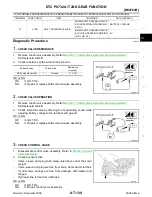
TERMINAL
WIRE COLOR
ITEM
CONDITION
DATA (APPROX.)
12
LG/B
SHIFT SOLENOID VALVE B
WHEN SHIFT SOLENOID VALVE
B IS OPERATING (DRIVING IN D
1
OR D
2
)
BATTERY VOLTAGE
WHEN SHIFT SOLENOID VALVE
B IS NOT OPERATING (DRIVING
IN D
3
OR D
4
)
0V
Solenoid valve
Terminal No.
Resistance
(Approx.)
Shift solenoid valve B
1
Ground
5 - 20
Ω
WCIA0091E
WCIA0092E
SAT367H

