background image

 Page 50

Quit Maker Pro 18 VERSA

System Information Screen

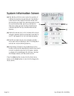
(A)  

The Lifetime stitch counter counts the number of 

stitches the machine has performed. The Lifetime 

count is the total number of stitches made since 

the machine was built. The Lifetime counter cannot 

be reset and should be used as an indicator to 

determine when general machine maintenance 

should be performed by an authorized Janome 

Retailer .

(B)

  The foot controller icon in the middle of the screen 

indicates whether the foot controller is attached. A 

red “X” will appear if it is not connected properly.

(C)

  The left and right sensor icons indicate whether 

the sensors are functioning. A red "X" will appear if 

sensors are not functioning properly.

(D)

  Information contained in the white boxes at the 

bottom of the screen identifies the electronics board 

revision numbers as well as the firmware revision 

numbers of the Quilt Maker Pro 18 Versa machine 

the display version, and the sensor version. 

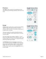
Press the 

Home

 button to return to the Main menu 

screen or the 

Tools

 button to return to the Diagnostics 

menu screen . 

A

D

B

C

Summary of Contents for Quilt Maker Pro 18 VERSA

Page 1: ...Janome Quilt Maker Pro 18 VERSA Service Manual...

Page 2: ...ck and Adjustment 19 Section 11 Timing Checking Loop Lift and Needle Distance 21 Section 12 Timing Adjusting First Rotate the Basket Down 22 Section 13 Timing Adjusting Loop Lift and Needle Distance 2...

Page 3: ...and described in the manual Do not jump ahead or start in the middle of the adjustment sequence this may cause additional or more serious problems than the original issue Safety must be considered wh...

Page 4: ...on Sew Foot Stroke Lift Needle Bar Stroke Take Up Stroke Lubrication main components Lubrication of hook 245 mm X 470 mm 8 25 X 18 Manual Mode Min 90 spm Max 2200 spm Regulated Mode Min 0 spm Max full...

Page 5: ...on assembly 3 hole thread guide motor pulley hook 3 5 mm hex tool socket head cap screw class 8 8 5 6 Nm uses 4 mm hex tool tool Front cover large Belt tensioner Drive train bracket 4 5 mm hex tool se...

Page 6: ...the above in box w booklet Lubricant Order Numbers The Quilt Maker Pro 18 VERSA lubricating schedule should be followed every year up to every two years to ensure top mechanical performance Machine C...

Page 7: ...mast support until the top eyelet loops are directly over the spool pins If the thread mast is too tight inside the bracket remove the screw push the mast out of the bracket until you can rotate the e...

Page 8: ...p lever the thread stirrup and the needle bar thread guide Check for any abrasions cuts or electroplating blistering Test each guide by flossing it with thread left to right and front to back in all d...

Page 9: ...the other 10 front cover screws 4mm handle hex tool you may need an L hex tool to loosen them first 4 Remove the two screws from the needle plate and then remove the needle plate 3 flat screwdriver 5...

Page 10: ...he hook less frequently After the lubrication of the hook it is recommended that one momentarily sew on scrap material before resuming the sewing of the quilt Failure to do so may result in oil stains...

Page 11: ...op per orifice articulating link take up lever and needle bar driver 3 places 4 Green IsoFlex NCA 15 Inside caged needle bearings 2 places 5 Orange GLY 151 Add grease sparingly to the presser bar slid...

Page 12: ...ated and tightened on a flat the second screw is then tightened compounding the tightness of the first screw thus securing and assuring that timing will not change Note The main shaft thrust collar ha...

Page 13: ...ey or the setting can be thrown off which may make it so needle to hook distance cannot be adjusted The QMP 18 VERSA utilizes long collars with two screws in line to help prevent the collar from tippi...

Page 14: ...nally set the screws Check that the shaft has minimal play and no tightness from the collar being too tight by rotating the shaft through a few 360o rotations Check that the timing of the eccentric is...

Page 15: ...red 5 mm handle hex tool Check 1 The base plate must be adjusted so that the rubber feet will sit flat on a planed surface Note This is done on a precision surface plate at the factory during assembly...

Page 16: ...he belt from the handwheel to the hook Important Do not over tighten the belt as this will make the machine too tight the handwheel more difficult to turn create more belt noise and also cause other u...

Page 17: ...it has about this number If it does not have 6 or 7 exposed threads this will alert you that someone has adjusted the adaptor in or out This may cause too much or too little tension on the internal pr...

Page 18: ...dle bar is at its lowest position 2 Place the 0 5mm feeler gauge part QM40133 under the hopping foot with the printed edge up 3 Loosen screw C through the machine front cover access hole 4 Wiggle the...

Page 19: ...needle for straightness on a flat surface such as the needle plate The needle must be centered in the stitch hole of the needle plate as shown in Figure 10 1 2 mm and 3 mm handle hex tool Check with...

Page 20: ...head frame If a correction is necessary Loosen screws F G and H through access holes Figure 10 4 2 or 3 turns Loosen screws D and E 2 or 3 turns and back off screw C a little Push the head frame back...

Page 21: ...lowing before attempting to make a hook timing adjustment 1 Remove the needle plate 2 Turn the hand wheel until the needle bar is at its lowest position or BDC Bottom Dead Center 3 Place the loop lift...

Page 22: ...n adjust the needle distance more accurately Figures 12 1 12 2 and 12 3 Important Note After moving the stop finger the basket can rotate and be hit by the needle you need to hold the basket in place...

Page 23: ...ssible to set needle distance correctly because needle distance is set so the hook point lightly brushes inside the needle scarf Adjusting Loop Lift and Needle Distance 1 If still in place from the ch...

Page 24: ...e with your other hand Carefully rotate the hook on the hook shaft to set the loop lift Carefully snug and then tighten the first screw 7 If timing and needle positions are still good remove the clamp...

Page 25: ...n Insert a screwdriver through the access hole Figure 14 2 Hold the needle bar with your other hand to provide resistance against the adjustment so the needle bar will not fall down out of the driver...

Page 26: ...completely loosened Failure to observe this caution can result in the uncoupling of the needle bar from the needle bar driver If this happens do not run the machine Remove the front frame cover reasse...

Page 27: ...l get stuck around the stop finger and may jam the machine If an adjustment is necessary Loosen screw A Figure 15 1 and adjust the stop finger so the proper clearance is achieved as shown in Figure 15...

Page 28: ...ce section Check loop lift If the machine requires a loop lift adjustment remove the stop finger and hook body from the machine Follow the steps below using the Needle Height Cylinder tool part number...

Page 29: ...arth Ground as well as the Line and Neutral prongs of the plug An improper or non existent earth ground connection will lead to sporadic and potentially dangerous operating conditions of the machine 4...

Page 30: ...d on you can rotate the hand wheel and see the green LEDs flash to indicate that the encoder is working properly The green Speed LED on the left side of the board should flash on and off at a rate of...

Page 31: ...dle Position Sensor Failure 2 Possible Issue Running the machine in manual mode the motor attains full speed prior to reaching 100 on the display a This can be caused by the Speed Needle sensor missin...

Page 32: ...power to the motor driver board the motor will not turn and a message on the handles will indicate either Needle Sense Failure or Needle Sense Failure During Walk If this happens check the output of...

Page 33: ...he name except the handlebars which are labelled J18 and J 17 RED BLK power connection top right of board Encoder speed needle sensor for main shaft Motor Driver Handle Bar Connection J18 Handle Bar C...

Page 34: ...that the 18V power is functioning and the right LED closest to the 5Vdc label indicates that the 5V power is functioning If either of these LEDs is not on first disconnect all cables from the control...

Page 35: ...e machine code This will prevent any communication from the second handle bar during the update process that might corrupt the machine code Differences Between the Front and Rear Handle Bar Display As...

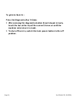
Page 36: ...Press the Diagnostics Bar 5 times After pressing the diagnostics button heart shape in tools touch the bar at the top of the screen 5 times or until the machine enters burn in mode To shut off burn i...

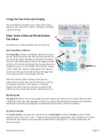
Page 37: ...hange back to the play icon with a blue background color When the machine foot controller is pressed the button color and icon show that the machine is running by changing the button to the pause icon...

Page 38: ...edle up at the specified interval Coordinate how quickly you move the quilt sandwich with how quickly the machine takes a basting stitch Experiment with the various speed options along with moving the...

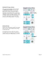
Page 39: ...rt indicating it is time to put in a new bobbin When recording a bobbin length REC will appear in this box When recording is turned off the bobbin remaining value will again appear in this space G H N...

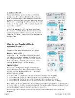
Page 40: ...stitches per inch SPI setting The setting is reflected in the white indicator box between the and buttons The value can be adjusted between 4 and 22 stitches per inch Basting Stitches There are four...

Page 41: ...inimum speed the machine will stitch regardless of how slowly the fabric is moving across the table The Cruise speed can be adjusted using the and buttons that appear below the Cruise button when Crui...

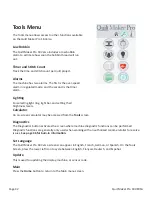
Page 42: ...and setting their brightness levels Calculator An on screen calculator may be accessed from the Tools screen Diagnostics The Diagnostics button activates the screen where machine diagnostic functions...

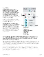
Page 43: ...ICONS A Record Stop B Bobbin Thread Capacity C New Bobbin D Save Preset E Set Alarm F Preset Value Put a new bobbin with the same thread into the machine and press the New Bobbin button C Then press t...

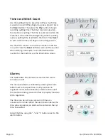
Page 44: ...number of stitches in a quilt Press the Reset button to zero out the counter when starting a new quilt To see the lifetime stitch counter for the machine see the Information screen Alarms The Quilt M...

Page 45: ...ddition subtraction multiplication division square root and percentage Use the back space on the top right to delete a digit mistakenly entered Diagnostics Screen Six different diagnostics tests can b...

Page 46: ...there is a problem with the Quilt Maker Pro 18 Versa speed sensor Before performing this test remove the bobbin case and the top thread Press the foot pedal so that the machine will begin slowly runni...

Page 47: ...nt beep or no beep at all for a full 360 rotation of the hand wheel this indicates a failed test and the machine should be inspected by a quali ed Janome repair technician The machine will beep as fab...

Page 48: ...f there is a problem with the Quilt Maker Pro 18 Versa foot pedal Slowly depress the foot pedal a percent of depression will appear in the white box The foot pedal should be controllable from 0 to 100...

Page 49: ...of the display as shown 2 Wait for the color of the selection buttons to change from gray to blue green 3 Select the machine display or sensor icon for update as needed 4 When the display update butto...

Page 50: ...e middle of the screen indicates whether the foot controller is attached A red X will appear if it is not connected properly C The left and right sensor icons indicate whether the sensors are function...

Page 51: ...ble using the Quilt Maker Pro 18 Versa quilters can begin with a few simple techniques using a sample quilt sandwich two pieces of fabric with a layer of batting between them Set the machine at a medi...

Page 52: ...sulting in fabric damage as well as skipped stitches thread breakage or shredding Always change the needle if it has been hit bumped or pulled off center while maneuvering the machine over the quilt A...

Page 53: ...the needle is pushed into the needle bar clamp until it can go no further Visually check that it is up to the top of the sight hole above the needle bar clamp screw If the needle isn t installed prope...

Page 54: ...will return fairly close to its preset tension Test the tension before quilting Hand Wheel Won t Rotate Corrective Measure s Thread is entangled and caught in the hook creating a thread lock Carefully...

Page 55: ...ad or thread that is rotted or brittle Top and bobbin tensions not balanced Balance the tension of the needle thread after ensuring the bobbin tension is adjusted correctly For more information about...

Page 56: ...is shredding at the throat plate check for burrs or jagged edges Gently rub with emery cloth to remove the sharp edge Consult a repair technician to polish any hard to reach or delicate areas or if t...

Page 57: ...Janome America com Page 57 Notes...

Page 58: ......

Reviews: