background image

JPC 100-WEB 

www.janitza.de

12

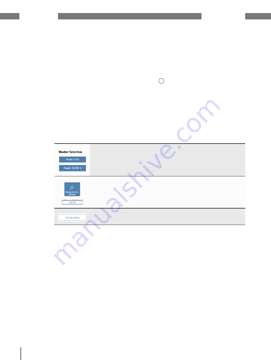
Select the respective master device using the names of the master devic-

es.

Use the Measurement -Details/Details buttons to retrieve further mea-

sured values of the respective device (the measured values displayed de-

pend on the device type). For master devices you can hide the measured 

value overview on the start page using the configuration options.

Open the configuration menu of the selected master device with the Con-

figuration button.

6. 1 

Start page

The start page (Fig. 09) shows an overview 
of all integrated devices that is structured as 
follows:

• Overview of the master devices in the 

upper area. Optionally, a measured value 
overview of the selected master device is 
displayed at this location.

• Tabular measured value overview of the 

slave devices assigned to the selected 
master device in the lower area. 

6. 2 

Remote access

To access JPC 100-WEB from a PC via the 
Ethernet connection, proceed as follows:

1.  Open a browser on the PC.
2.  Enter the following in the ad-

dress line: http://[IP address of the 
JPC 100-WEB]:8080/jpc.html 

For an explanation of how to determine the IP 
address of your JPC 100-WEB, see section 
7. 1. 3.

6. 3 

Log in

Log in to the interface to make changes to 
the system settings and the configuration of 
the devices and alarms.

Open the log-in window via the 

Settings 

(Fig. 

09 

1

) and then the 

User settings

 tab.

Once you have entered valid login data in the 
login window, you are automatically logged in 
to the interface.

For more information, see 7. 2 Users (login to 
the system) on page 17.

Summary of Contents for JPC 100-WEB

Page 1: ...05 2020 Smart Energy Panel JPC 100 WEB User manual and technical specifications Janitza electronics GmbH Vor dem Polst ck 6 D 35633 Lahnau Support tel 49 6441 9642 22 Email info janitza de www janitza...

Page 2: ...coming goods inspection 7 3 5 Scope of delivery 7 4 Mounting 8 4 1 Installation location 8 4 2 Mounting orientation 8 4 3 Securing 9 5 Installation 10 5 1 Disconnect switch 10 5 2 Supply voltage 10 5...

Page 3: ...as a master device 23 9 2 Slave devices 24 9 2 1 Integrating a new slave device 25 9 2 2 Configuring the UMG 20 CM 25 9 3 Alarms and warnings 26 10 Service and maintenance 27 10 5 Remote access via T...

Page 4: ...hts arising from them are the property of the respective own ers of these rights 1 3 Technical changes Make sure that your device matches the installation instructions First read and understand the do...

Page 5: ...ing the user manual Read it before using the device Retain it for the entire service life of the product and keep it at hand ready for reference When using the device also observe the le gal and safet...

Page 6: ...rdous voltage Consequently severe bodily injury or material damage can occur if they are not handled properly 2 3 Qualified personnel This device must be operated and main tained exclusively by qualif...

Page 7: ...ation and maintenance Exercise due caution when unpacking and packing the device do not use force and only use suitable tools Check the devices for flawless mechanical condition by visual inspection C...

Page 8: ...e JPC 100 WEB CAUTION Material damage due to disregard of the installation instructions Disregard of the installation instructions can damage or destroy your device Observe the information on the moun...

Page 9: ...l lation cutout from the front 2 Insert the retaining brackets into the openings on the device provided for this purpose Fig 3 Inserting the retaining brackets 3 Push the retaining brackets towards th...

Page 10: ...er supply Install the circuit breaker near the device and within easy reach of the user Mark the circuit breaker as the disconnect ing device for this measuring device 5 2 Supply voltage A supply volt...

Page 11: ...page 24 1 Settings menu depending on the user role this menu is labeled Administrator Read only or Operator 2 Menu bar 3 Selected master device 4 Measured value overview of the selected master device...

Page 12: ...view of the selected master device is displayed at this location Tabular measured value overview of the slave devices assigned to the selected master device in the lower area 6 2 Remote access To acce...

Page 13: ...h areas 7 Settings 7 1 System Use the System tab to configure the basic settings of the JPC 100 WEB such as inter faces time setting or language The menu is divided into the areas Device Modbus TCP IP...

Page 14: ...2 Use the Open File Explorer Fig 10 but ton to open the file system Fig 12 The Export device configuration pop up window Importing configuration To import a configuration file it must be avail able o...

Page 15: ...ts in the IT network Consult your network administrator for the correct network settings for your device 7 1 3 TCP IP The TCP IP area shows the current IP ad dress and subnet mask of the JPC 100 WEB D...

Page 16: ...you can perform the following actions by touching the corresponding entry Select between automatic and manual time and date setting Select between automatic and manual time zone Change the NTP server...

Page 17: ...gged in This role allows viewing of measured values system settings and alarms Operator Standard role for logged in users They can also acknowledge and configure alarms and warnings as well as configu...

Page 18: ...en the user management via the User Management button on the User settings tab In this case a new login with administrator access data is necessary Fig 21 User Management To change the username or pas...

Page 19: ...requires access to a SMTP server to be able to send e mails You must define an interval at which JPC 100 WEB checks whether new warnings or alarms are present All new unacknowl edged warnings and alar...

Page 20: ...ledge all alarms at once by pressing the Acknowledge All button or ac knowledge individual alarms by pressing the check mark after the corresponding alarm Use the Historic Alarms button to open a list...

Page 21: ...devices in the JPC 100 WEB and to configure integrated devices Call Start page Configuration You must be logged in to the device as an administrator to configure measurement devices Use the tabs Maste...

Page 22: ...measurement devices using Modbus RTU the master device JPC 100 WEB and slave devices must have the same baud rate The respective user information describes how to determine the baud rate of the respec...

Page 23: ...Optional Activate deactivate the link to the device homepage in the measured value details Only for measurement devices with a device homepage 7 Save the configuration The master device is now displa...

Page 24: ...you want to configure in the JPC 100 WEB You can switch between the different measure ment channels of the UMG 20 CM quickly using the arrow buttons Use this drop down menu to assign the slave de vic...

Page 25: ...nimum maximum current mea surement values for all UMGs and to transfer the current configuration to all UMGs Use the Actions for this UMG button to reset ener gy meters and minimum maximum current mea...

Page 26: ...enu to select which mea sured value is to be monitored Here you can configure the upper and lower limits for alarms and warnings for each measured value To facilitate selection the list of measured va...

Page 27: ...and calibration Repairs and calibration can only be carried out by the manufacturer 10 3 Front panel foil The front panel foil can be cleaned with a soft cloth and standard household cleaning agents...

Page 28: ...t s RS 485 Protocol Modbus RTU master 3 lead connection with GND B A Transmission rate1 9 6 kbps 19 2 kbps 38 4 kbps 57 6 kbps 115 2 kbps 230 4 kbps Display Type TFT color Diagonal 10 Resolution 1024...

Page 29: ...31 Side view Fig 30 Rear view 282 mm 11 10 in 70 mm 2 76 in 184 mm 7 24 in 70 mm 2 76 in 35 mm 1 38 in 1 2 3 4 5 6 Fig 32 Bottom view 1 Ethernet 2 USB 2 0 type A 3 Micro USB 4 24 V supply voltage ter...

Reviews: