Pro I: Digital-I/O- and Counter Modules
Pro-CNT-PW4-I Rev. A
ADwin
124
ADwin-Pro
Hardware, manual version 2.9, June 2006
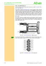
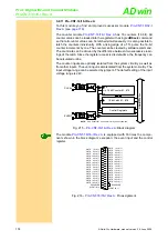
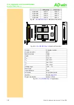
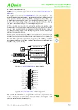
Fig. 237 –
: Board and front panel
falling edge
rising edge
Input PW1
Latch 1
Latch 5
Input PW2
Latch 2
Latch 6
Input PW3
Latch 3
Latch 7
Input PW4
Latch 4
Latch 8
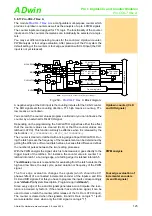
Fig. 236 –
: Allocation of the latches
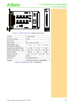
Counter
4 impulse counter
Counter resolution
32 bit
Event inputs
1
Reference clock
5MHz
Input current
typ. 7mA / max. 15mA
input voltage range
(selectable via jumpers)
0…5V
0 … 12V
0…24V
Switching threshold 0 (low)
0 … 0.8V
0 … 1.6V
0 … 3.2V
Switching threshold 1 (high)
4.5 … 5V
10 … 12V
20 … 24V
Series resistor
560
Ω
2k
Ω
4.3k
Ω
Input over-voltage
8V
16V
30V
Negative voltage
-5V for all ranges
Switching time
200ns
Isolation
42V channel-channel / channel-GND
Connector
37-pin DSub socket
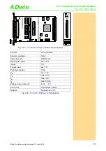
: Specification
19CNT01
ON
1 2 3 4 5 6 7 8
A0 A1 A2 A3 A4 A5 A6 A7
FPGA
FPGA
74A
B
T
16245
74LS19
74LS19
74LS19
74LS19
74LS19
74LS19
74LS19
OCX
FPGA
FPGA
FP
G
A
HCPL-2631
HCPL-2631
HCPL-2631
HCPL-2631
19CNTII1
HCPL-2631
+5
V
+1
2
V
+2
4
V
74LS19
HCPL-2631
HCPL-2631
HCPL-2631
HCPL-2631
+5
V
+
12V
+
24V
+5
V
+
12V
+
24V
+5
V
+
12V
+
24V
+5
V
+
12V
+
24V
+5
V
+
12V
+
24V
+5
V
+
12V
+
24V
+5
V
+
12V
+
24V
+5
V
+
12V
+
24V
+5
V
+
12V
+
24V
+5
V
+
12V
+
24V
+5
V
+
12V
+
24V
+5
V
+
12V
+
24V
+5
V
+
12V
+
24V
+5
V
+
12V
+
24V
+5
V
+
12V
+
24V
+5
V
+
12V
+
24V
74LS19
74LS19
19/37
18/36
17/35
16/34
15/33
14/32
13/31
12/30
11/29
10/28
9/27
8/26
7/25
6/24
5/23
4/22
20/1
Sub-D-
Pin-Nr.:
Sub-D-
Pin-Nr.:
Sub-D-Pin-Nr.:
CNT-PW4-I
COUNTER
INPUT

