HYDROSTATIC POWER TRAIN
4181384 First Edition
5-15
5
Figure 5-14
6.
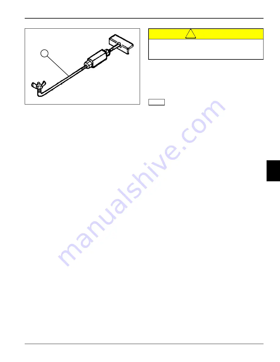
Adjust flow lock tool (6) to allow pump to produce 10
gpm (37.8 lpm) in the forward direction.
7.
Use the flow meter to warm the hydraulic oil. Turn the
flow meter valve (2) until a reading of 1525 psi (105
bar) or one half of the relief valve rating is reached.
Warm oil to 120—150°F (49—65°C), open valve fully
after operating temperature is reached.
8.
After warming the hydraulic oil, verify flow lock tool is
adjusted to allow pump to produce 10 gpm (37.8 lpm)
in the forward direction.
9.
Read and record no load flow.
10. Slowly close flow meter valve (2) until pressure
reaches 2300 psi (159 bar). Read and record loaded
flow.
11. Stop engine and return flow lock tool back to neutral
position.
12. Calculate traction pump leakage.
(Step 9 – Step 10 / Step 9 x 100 = Leak Percentage)
Is traction pump leakage 10% or less?
YES
The traction pump is good. Proceed to step
13.
NO
Proceed to next question.
Is traction pump leakage 11% to 20%?
YES
The traction pump is marginal. Additional
testing is required. Continue to step 13.
NO
Proceed to next question.
Is traction pump leakage 21% or more?
YES
Repair or replace traction pump. (See
“Traction Pump” on page 5-22.)
!
CAUTION
13. Continue to close flow meter valve (2) until zero flow
is obtained. Record forward system relief valve
pressure.
14. Stop engine and return flow lock tool back to neutral
position.
NOTE
Reverse system relief valve test is similar.
15. To test reverse system relief valve, swap hoses (4)
and (5) at flow meter and adjust flow lock tool to 10
gpm (37.8 lpm) in reverse direction.
16. Close flow meter valve (2) until zero flow is obtained
and record reverse system relief valve pressure.
17. Stop engine and return flow lock tool back to neutral
position.
Is forward system relief pressure 3046 psi (210
bar)?
YES
Forward system relief valve is good. Proceed
to step 18.
NO
Replace forward system relief valve. (See
“Traction Pump” on page 5-22.)
Is reverse system relief pressure 3046 psi (210
bar)?
YES
Reverse system relief valve is good. Proceed
to step 18.
NO
Replace reverse system relief valve. (See
“Traction Pump” on page 5-22.)
18. If no further testing is required, disconnect and
remove test equipment. Install all hoses and fittings
as noted prior to removal.
19. Check hydraulic oil level. Add oil as needed. (Refer to
“Safety, Operation, and Maintenance Manual” for oil
specifications.)
6
TN1364
Do not exceed 3100 psi (214 bar) when testing
system relief valves or equipment damage may
occur.
Summary of Contents for AR3
Page 1: ...AR 3 TR 3 Trim Mowers Technical Repair Manual AR30001 AR30002 TR30001 TR30002...
Page 3: ......
Page 7: ......
Page 9: ...1 2 4181384 First Edition SAFETY 1 Page Intentionally Blank...
Page 19: ...1 12 4181384 First Edition SAFETY 1...
Page 33: ...2 14 4181384 First Edition SPECIFICATIONS AND GENERAL INFORMATION 2 Page Intentionally Blank...
Page 73: ...4 16 4181384 First Edition ELECTRICAL 4 Page Intentionally Blank...
Page 85: ...4 28 4181384 First Edition ELECTRICAL 4 Page Intentionally Blank...
Page 147: ...4 90 4181384 First Edition ELECTRICAL 4 Page Intentionally Blank...
Page 200: ...HYDRAULICS 4181384 First Edition 6 9 6 Page Intentionally Blank...
Page 249: ...6 58 4181384 First Edition HYDRAULICS 6 Page Intentionally Blank...
Page 251: ...7 2 4181384 First Edition STEERING 7 Page Intentionally Blank...
Page 264: ...STEERING 4181384 First Edition 7 15 7 Page Intentionally Blank...
Page 265: ...7 16 4181384 First Edition STEERING 7...
Page 311: ...8 46 4181384 First Edition CUTTING UNITS 8 Page Intentionally Blank...
Page 331: ...9 20 4181384 First Edition ACCESSORIES AND MISCELLANEOUS REPAIR 9 Page Intentionally Blank...
Page 340: ......
Page 342: ......


