background image

57

07610-004-33-05-E

ITEM

QTY

DESCRIPTION

PART NUMBER

1

14

Locknut, 1/4-20 Hex with Nylon Insert

05310-374-01-00

2

14

Washer, 1/4-20

05311-174-01-00

3

14

Washer, Flat, 0.406 ID x 0.750 OD

05311-004-29-35

4

7

Rack Catch, Left

05700-004-29-32

5

7

Rack Catch, Right

05700-004-29-33

6

14

Bolt, Shoulder, 3/8" x 1/4", 1/4-20

05306-004-29-34

7

1

Pawl Bar Weldment

05700-004-17-74

8

1

Rack Drive Guide

05700-004-29-36

9

2

Bolt, Rack Drive Guide, 1/4-20 x 3/4" (Not Shown)

05310-011-44-35

10

2

Lockwasher, Rack Drive Guide, Spring, 1/4" (Not Shown)

05311-274-01-00

PARTS

PAWL BAR

1

2

3

6

7

4

5

8

Complete Pawl Bar Assembly

05700-004-17-75

Summary of Contents for RackStar 44

Page 1: ...RACKSTAR RackStar Manual 07610 004 33 05 E INSTALLATION OPERATION AND SERVICE MANUAL RACKSTAR SERIES CONVEYOR DISHMACHINES ...

Page 2: ...talled by Jackson at the factory and are shipped with the Dishmachine carry only a 1 one year parts warranty Labor to repair or replace these components is not included in the warranty or covered by Jackson Booster heaters not manufactured by Jackson are not covered by this warranty but are warranted by their respective manufacturers This warranty is void if any defect or failure is a direct resul...

Page 3: ...E RESULTS FROM DEFECTS IN MATERIALS AND WORKMANSHIP AND IS REPORTED TO JACKSON WITHIN 30 THIRTY DAYS FROM THE DATE OF INSTALLATION 9 DAMAGE CAUSED BY LABOR DISPUTE 10 DAMAGES RESULTING FROM IMPROPER CONNECTION TO UTILITY SERVICE 11 DAMAGES RESULTING FROM WATER CONDITIONS INADEQUATE OR EXCESSIVE WATER PRESSURE ACCIDENTS ALTERATIONS IMPROPER USE ABUSE HANDLING OVERLOADS TAMPERING IMPROPER INSTALLATI...

Page 4: ...ced item 12 on pgs 59 and 60 with new part Added Drive Plate components to pg 60 Added communication cable to Display Assembly page Added a Frame Assembly page Replaced item 7 on pg 66 with new part Changed P N of Drive Link on pg 67 Added Booster Heater Add on Kit to pg 70 Updated schematics D 3 13 18 JH N A Updated dimensional drawings with depiction of drain air gap and associated specification...

Page 5: ...available on holidays Contact technical support toll free at 1 888 800 5672 Technical support is available for service personnel only RackStar 44 RackStar 66 Electrically heated rack conveyor machine available in chemical sanitizing and hot water sanitizing models RackStar 44ER RackStar 66ER Electrically heated hot water sanitizing rack conveyor machine with Energy Recovery System RackStar 44S Rac...

Page 6: ...stallation Instructions 19 Inspection 19 Unpacking 19 Leveling 19 Adjusting Doors 19 Plumbing 19 Drain Line Connection 20 Steam Line Connection 21 Electrical Power Connections 21 Motor Rotation 22 Ventilation 22 Thermostats 22 Table Limit Switch Option 22 Chemical Feeder Equipment 23 Connection Points 23 External Device Wiring 24 Exhaust Fan Timer 24 Curtain Installation 25 OPERATION Operating Ins...

Page 7: ...bleshooting 32 Programming 34 Fault Codes 36 PARTS Control Box 38 Display 39 Miscellaneous Electrical Components 40 Wash Heater Shroud 41 Wash Heaters 42 Pump Suction 43 Plumbing 44 Pre wash Fill Plumbing 46 Energy Recovery Plumbing 47 Wash System 50 Pre wash System 52 Rinse System 54 Plumbing Options 56 Pawl Bar 57 Rack Rails 58 Drive Assembly 60 Ventilation Cowl 62 Ventilation Cowl for Unhooded ...

Page 8: ...l 69 Booster Heater Electric 70 Booster Heater Add on Kit Electric 71 Frame 72 Doors 73 Energy Recovery System 74 Miscellaneous Options 76 SCHEMATICS 208 230 V 50 60 Hz 3 Phase 77 460 V 50 60 Hz 3 Phase 78 600 V 50 60 Hz 3 Phase 79 Steam 80 Side loader 81 ADDENDUM Display Template 82 ...

Page 9: ...Power Hz Hertz ID Inside Diameter kW Kilowatts MIN Minimum NFPA National Fire Protection Association NPT National Pipe Thread ppm Parts per Million PSI Pounds per Square Inch V Volts 40º 40 degree Rise 70º 70 degree Rise 5 5 CAUTION WARNING NOTICE Risk of Injury to Personnel Risk of Damage to Equipment Risk of Electrical Shock Lockout Electrical Power Reference Data Plate Important Note i Caustic ...

Page 10: ...nt Standard also uses secondary opening for a separate connection to only the booster LEGEND A Electrical Connection B Main Water Inlet 1 2 NPT 110 F MIN 18 kW Booster 140 F MIN 12 kW Booster or 180 F MIN No Booster or Supplied from Steam Booster C Drain Connection 1 1 2 NPT D Vent Connections Including Dampers E Steam Connection 3 4 NPT Open Door High Hood Option All dimensions from the floor can...

Page 11: ...nt Standard also uses secondary opening for a separate connection to only the booster LEGEND A Electrical Connection B Main Water Inlet 1 2 NPT 110 F MIN 18 kW Booster 140 F MIN 12 kW Booster or 180 F MIN No Booster or Supplied from Steam Booster C Drain Connection 1 1 2 NPT D Vent Connections Including Dampers E Steam Connection 3 4 NPT Open Door High Hood Option All dimensions from the floor can...

Page 12: ...m Primary Electrical Opening Provided on both ends of machine Secondary Electrical Opening Provided on both ends of machine Single point Option uses only primary opening to power the entire machine Dual point Standard also uses secondary opening for a separate connection to only the booster LEGEND A Electrical Connection B Main Water Inlet 1 2 NPT 110 F MIN 18 kW Booster 140 F MIN 12 kW Booster or...

Page 13: ...ction 3 4 NPT Open Door High Hood Option All dimensions from the floor can be increased 1 3 4 using the machine s adjustable feet Items in red are not supplied with the machine Items in blue are for the Steam option 4 MIN 102 mm 12 305 mm 39 3 4 1009 mm 16 406 mm 20 508 mm 15 381 mm 30 762 mm 66 1676 mm 86 2184 mm 4 102 mm 5 127 mm 15 1 8 384 mm 8 202 mm 6 7 8 210 mm 43 3 8 1101 mm ADJUSTABLE FROM...

Page 14: ...5 F MIN increased 1 3 4 using the machine s adjustable feet Items in red are not supplied with the machine LEGEND Primary Electrical Opening Provided on both ends of machine Secondary Electrical Opening Provided on both ends of machine Single point Option uses only primary opening to power the entire machine Dual point Standard also uses secondary opening for a separate connection to only the boos...

Page 15: ...e entire machine Dual point Standard also uses secondary opening for a separate connection to only the booster 34 1 4 870 mm TABLE HEIGHT A Electrical Connection B Water Inlet 1 2 NPT 110 F MIN 27 kW Booster C Drain Connection 1 1 2 NPT D Vent Connections Including Dampers E Energy Recovery Water Inlet 1 2 NPT 55 F MIN increased 1 3 4 using the machine s adjustable feet Items in red are not suppli...

Page 16: ...primary opening to power the entire machine Dual point Standard also uses secondary opening for a separate connection to only the booster A Electrical Connection B Water Inlet 1 2 NPT 110 F MIN 27 kW Booster C Drain Connection 1 1 2 NPT D Vent Connections Including Dampers E Energy Recovery Water Inlet 1 2 NPT 55 F MIN increased 1 3 4 using the machine s adjustable feet Items in red are not suppli...

Page 17: ...g to power the entire machine Dual point Standard also uses secondary opening for a separate connection to only the booster A Electrical Connection B Water Inlet 1 2 NPT 110 F MIN 27 kW Booster C Drain Connection 1 1 2 NPT D Vent Connections Including Dampers E Energy Recovery Water Inlet 1 2 NPT 55 F MIN increased 1 3 4 using the machine s adjustable feet Items in red are not supplied with the ma...

Page 18: ... 23 L R UNHOODED SIDE LOADER 23 R L UNHOODED SIDE LOADER Ventilation Scoop Ventilation Scoop Ventilation Cowl with Cut out for L R Units Dimension is 30 for the 30 unhooded side loader Dimension is 30 for the 30 unhooded side loader Electrical Conduit Adjustable Ventilation Duct Adapter Ventilation Cowl with Cut out for R L Units Side loader Drain Hose Electrical Conduit 34 1 ...

Page 19: ...28 5 8 201 4 W1 S W2 PS PW 33 11 3 8 22 71 2 E E E 11 16 3 8 E Main Electrical Connection 7 8 Hole W1 Main Inlet Water Connection 3 4 NPT 110 F MIN 20 5 PSI W2 Water Outlet Connection 3 4 NPT PW Water Pressure Relief Outlet 3 4 NPT PS Steam Pressure Relief Outlet 1 NPT S Steam Supply to Booster 1 NPT C Steam Condensate Connection 3 4 NPT Click here for the Steam Booster manual ...

Page 20: ...5 575 5 575 5 575 5 575 Glasses per Hour 8 028 8 028 8 028 8 028 8 028 8 028 Tank Capacity Gallons RackStar 44 RackStar 66 RackStar 44S RackStar 66S RackStar 44ER RackStar 66ER Wash Tank 25 25 25 25 25 25 Pre wash Tank N A 15 8 N A 15 8 N A 15 8 Electrical Loads RackStar 44 RackStar 66 RackStar 44S RackStar 66S RackStar 44ER RackStar 66ER Wash Motor HP 3 3 3 3 3 3 Drive Motor HP 1 4 1 4 1 4 1 4 1 ...

Page 21: ...er N A N A Minimum Incoming Cold Water Temperature ER Units Only N A N A N A N A 55 55 CHEMICAL SANITIZING Water Temperatures F RackStar 44 RackStar 66 RackStar 44S RackStar 66S RackStar 44ER RackStar 66ER Pre wash Temperature N A 110 140 N A N A N A N A Minimum Wash Temperature 120 120 N A N A N A N A Incoming Rinse Temperature 120 120 N A N A N A N A Minimum Incoming Water Temperature 110 110 N ...

Page 22: ...olts Always verify the amperage draw of the machine in operation when sizing circuit protection If the machine is equipped with a booster heater note the heater has its own electrical connection and therefore requires a separate service single point connection is available as an option on three phase machines only Amperage loads for motors and heaters are listed on the machine data plate for the i...

Page 23: ...hout notice If using a third party external booster consult booster manufacturer for booster information With dual point connection standard Booster Heater has its own connection Imbalanced wild leg goes to L3 Also see the Motor Rotation section 5 5 RackStar 44 Dual point Connection Standard Booster Heater MCA MOP 47 9 A 49 2 A 50 A 43 3 A 44 6 A 45 A 21 7 A 23 0 A 25 A Volts Phase Freq Wash Motor...

Page 24: ...rive Motor Wash Heater Total Load MCA MOP 208 3 60 Hz 6 2 A 9 2 A 1 1 A 41 6 A 58 1 A 60 4 A 65 A 230 3 60 Hz 6 2 A 8 6 A 1 1 A 34 6 A 50 5 A 52 6 A 60 A 460 3 60 Hz 3 1 A 4 3 A 0 7 A 17 3 A 25 4 A 26 5 A 30 A Booster Heater MCA MOP 47 9 A 49 2 A 50 A 43 3 A 44 6 A 45 A 21 7 A 23 0 A 25 A Booster Heater MCA MOP 33 3 A 34 6 A 35 A 28 9 A 30 2 A 35 A 14 4 A 15 7 A 20 A Booster Heater MCA MOP 74 9 A ...

Page 25: ...0 A 460 3 60 Hz 4 3 A 0 7 A 17 3 A 32 5 A 54 8 A 55 9 A 60 A Volts Phase Freq Wash Motor Drive Motor Wash Heater Booster Heater Total Load MCA MOP 208 3 60 Hz 9 2 A 1 1 A 41 6 A N A 51 9 A 54 2 A 60 A 230 3 60 Hz 8 6 A 1 1 A 34 6 A N A 44 3 A 46 4 A 55 A 460 3 60 Hz 4 3 A 0 7 A 17 3 A N A 22 3 A 23 4 A 25 A Volts Phase Freq Wash Motor Drive Motor Wash Heater Booster Heater Total Load MCA MOP 208 3...

Page 26: ...A 48 2 A 50 A Volts Phase Freq PW Motor Wash Motor Drive Motor Wash Heater Booster Heater Total Load MCA MOP 208 3 60 Hz 6 2 A 9 2 A 1 1 A 41 6 A 33 3 A 91 4 A 93 7 A 100 A 230 3 60 Hz 6 2 A 8 6 A 1 1 A 34 6 A 28 9 A 79 4 A 81 5 A 90 A 460 3 60 Hz 3 1 A 4 3 A 0 7 A 17 3 A 14 4 A 39 8 A 40 9 A 45 A Volts Phase Freq PW Motor Wash Motor Drive Motor Wash Heater Booster Heater Total Load MCA MOP 208 3 ...

Page 27: ...designed to operate while level This is important to prevent any damage to the machine during operation and to ensure the best results The machine comes equipped with adjustable bullet feet which can be turned using a pair of pliers Verify the machine is level from front to back and side to side before making any electrical or plumbing connections A level machine is important for proper door funct...

Page 28: ...to the proper flow pressure indicated on the data plate The water supply line must be 1 2 NPT minimum and must be able to provide water at the minimum temperature indicated on the machine data plate A shut off valve not supplied should be installed to isolate the machine from the water system in the event service is required An optional shock absorber not supplied should also be installed on the i...

Page 29: ...ing voltage matches the voltage indicated on the decal next to the incoming power pre punched hole For dual point connection machine has a separate power connection from the rinse booster heater and the circuit protection requirements are different for each Refer to the machine data plate for information on minimum circuit protection CAUTION Improperly connecting external devices can cause damage ...

Page 30: ... venting This is essential to permit efficient removal of the condensation exhaust Ensure the exhaust system is acceptable in accordance with applicable codes and standards Any damage caused by steam and or moisture due to improper ventilation is NOT covered under the warranty Dishmachine ventilation requirements Load End 200 CFM Unload End 200 CFM The exhaust system must be sized to handle this v...

Page 31: ...sers must be set for the type and concentration of chemicals being used Detergent usage and water hardness are two factors that contribute greatly to how efficiently the machine will operate Using the proper amount of detergent can be a source of substantial savings A qualified water treatment specialist can explain what is needed to gain the maximum efficiency from detergent The machine can opera...

Page 32: ...izer tube connections shown to the right Rinse aid and detergent dispenser connections shown to the right EXHAUST FAN TIMER RED BLK WHT WHT BLK WHT BLK GRY RED YEL RED DETERGENT DISPENSER CONNECTION LIVE WHEN WASH PUMP MOTOR IS ON FUSE 200 mA SLOW ACTING 120 VAC OUT RINSE AID DISPENSER CONNECTION LIVE WHEN RINSE VALVE IS OPEN FUSE 200 mA SLOW ACTING 120 VAC OUT CONSTANT VOLTAGE CONNECTION LIVE WHE...

Page 33: ...e heat necessary to keep energy costs down Note the approximate locations for each type of curtain in the above illustrations See the chart below for actual curtain lengths and part numbers Note the different part numbers for the curtain and curtain rod for the load end when a side loader option is present Legend Length Part S 12 08415 131 73 44 M 19 08415 002 14 41 XL 24 25 08415 002 47 37 2X 29 ...

Page 34: ...mode of operation the wash heater will energize Refer to the machine data plate for a better understanding of the minimum temperatures needed to operate the machine correctly It might take several minutes for the wash tank to heat up depending on the initial temperature of the water 3 If the machine is equipped with a rinse booster option the booster will turn on when the machine turns on 4 If the...

Page 35: ...chine This machine is designed to wash ware that is placed in a rack Materials should not be placed in the machine unless they are properly secured in a dish rack To start the cycle gently push the rack into the machine on the load end Once the wash actuator has moved sufficiently the machine will automatically begin to convey the dish rack through the machine The entire cycle is automatic Operato...

Page 36: ...tank for debris 6 Remove curtains scrub with mild detergent and brush and allow to air dry 7 Wash Rinse Arms a As needed fill the tub with water b Remove the end caps from the arms c Run an empty rack through the machine d If necessary i Clean nozzles with a brush ii Use a small wire or toothpick to remove remaining debris or lime deposits from the nozzles iii Flush the arms with water iv Replace ...

Page 37: ...ctional 2 The machine will then go into Standby Mode blank display 3 Press the Power Button 4 The display will show Heating until the wash tank reaches operating temperature 5 The display will show Ready when the machine is ready to use HEATING CYCLE 1 180 F READY CYCLE 1 125 F DISPLAY INSTRUCTIONS Power Button Delime Button Cycle Light Rinse Options OPERATION OPERATING INSTRUCTIONS SHUTDOWN CLEAN...

Page 38: ...mmended by the chemical supplier 6 The wash tank holds 25 gallons and pre wash tank holds 15 8 gallons of water After chemicals are added 7 Make sure doors are closed 8 Press Delime Button and run machine the length of time recommended by chemical supplier 9 Press Delime Button again to stop the deliming process 10 Press Power Button to shut the machine off 11 Wait five minutes open the doors and ...

Page 39: ...er temperature could be too low 2 Ensure all strainers are clean and in place laying flat before operating the machine When cleaning out strainers do NOT beat them on waste cans Wipe out strainers with a rag and rinse under a faucet if necessary Use a toothpick to dislodge any stubborn debris 3 Ensure all wash and rinse arms are secure in the machine before operating 4 Ensure drains are closed bef...

Page 40: ...amaged 2 Wash motor contactor faulty 1 Verify that the wash motor is getting power if so replace the motor 2 Check for continuity if contacts are open replace the contactor Dishmachine runs continuously in the wash cycle 1 Machine is in Delime mode 1 Select an automatic cycle by choosing I or II on the display Wash heater does not work 1 Faulty heater element 2 Faulty heater contactor 1 Check elem...

Page 41: ...ace the seal 2 Tighten 3 Tighten the hose clamps Will not rinse 1 Defective rinse solenoid 2 Faulty timer 3 No water to the machine 1 Repair or replace the rinse solenoid 2 Replace timer 3 Verify that there is water at 15 PSI connected to the machine Dishes are not coming clean 1 Machine temperatures are not up to the minimum requirements 2 No detergent or too much detergent 1 Verify that incoming...

Page 42: ... buttons Up arrow Down arrow and Select are hidden on the display and are shown below outlined with red dots 1 Press and hold the I and II Buttons until Program starts flashing 2 3 seconds 2 Press the Select Button 3 Use the Up arrow Button to change the program number to 5 for low temp machines or 6 for high temp machines 4 Press the Select Button 5 Program will flash 6 Press the Delime Button to...

Page 43: ...tton to cycle through the categories will be flashing Language Wash Offset Temperature Scale Rinse Offset Wash Temperature Boost Offset Boost Temperature Spare Offset 4 Press the Select Button to choose the category you want to change Regardless of the category Steps 5 7 remain the same 5 Use the Up arrow Button to change the options will be flashing Numerical options are shown in the top window 6...

Page 44: ...t output from IO module turns off when above the set temperature 2 Substitute a 1 2 kΩ resistor for T1 and verify that wash heater turns off If not replace IO module 3 Verify that T1 resistance is correct with respect to temperature see table on next page If not replace T1 F8 No water in wash tank Check inlet water and door 1 Malfunction of fill solenoid or fill relay 2 Door is open which inhibits...

Page 45: ...4 33 05 E 37 RESISTANCE TO TEMPERATURE VALUES R kΩ F 11 58 69 8 10 37 75 2 9 30 80 6 7 78 89 6 3 05 140 0 2 54 150 8 2 18 159 8 1 58 179 6 1 45 185 0 1 33 190 4 1 16 199 4 0 96 212 0 FAULT CODES TROUBLESHOOTING ...

Page 46: ... 1 I O Module 06401 004 76 12 5 2 Relay 05945 111 72 51 6 1 Timer Universal Digital Multi timer 05945 004 22 78 7 1 Overload See Motor Overloads page 8 2 Contactor Wash Motor 05945 111 68 38 9 1 Overload See Motor Overloads page 10 1 Transformer 208 V 05950 011 75 59 Transformer 230 460 V 05950 011 68 35 11 1 Contactor 3 pole 50 A 05945 002 24 70 12 1 Fan 05999 004 30 62 13 1 Relay 05945 111 35 19...

Page 47: ...05310 002 83 12 2 1 Board Populated Circuit 05945 004 46 18 3 4 Spacer Display Board 05999 004 19 75 4 1 Membrane Switch and Panel Assembly 05700 004 59 65 5 1 Communication Cable 05700 004 33 64 1 Cover Display Board Not Shown 05700 004 35 60 1 2 3 4 5 Complete Display Assembly 05700 004 31 50 ...

Page 48: ...5930 111 68 44 2 1 Float Switch 06680 121 70 71 3 1 Float Switch Cover 05700 004 71 80 4 1 Probe Fitting Brass 05310 924 02 05 5 1 Thermistor Probe 06685 004 34 58 6 6 Fuse 200 mA Slow acting 05999 004 44 33 7 2 Fuse 1 A Fast acting 05999 004 47 87 1 2 3 4 5 Parts are not shown to scale with relation to each other 6 7 ...

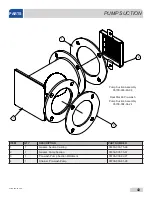
Page 49: ...89 4 1 Gasket Pump Suction 05330 003 75 87 5 1 Gasket Heater 05330 200 02 70 6 1 Heater Box Rails 05700 003 74 72 7 1 Wash Pump Suction 05700 003 77 63 8 2 Washer 1 4 20 05311 174 01 00 9 9 Locknut 1 4 20 Hex with Nylon Insert 05310 374 01 00 10 6 Nut Hex 5 16 18 05310 275 01 00 11 6 Lockwasher 5 16 Split 05311 375 01 00 12 1 Wash Heating Element 15 kW See Wash Heaters page 13 1 Thermostat High li...

Page 50: ...g wash heaters it is highly recommended to change the gasket as well Once installed gaskets become compressed and are subject to extreme temperature changes Replacing the gasket with the heater might prevent future leaks The nuts used to secure the heater to the casting should be torqued to 16 in lbs After tightening the machine should be allowed to heat up and operate normally for approximately 3...

Page 51: ...ting 05330 003 75 89 2 1 Gasket Pump Suction 05330 003 75 87 3 1 Pre wash Pump Suction Weldment 05700 003 82 27 4 1 Strainer Pre wash Pump 05700 003 81 28 4 1 3 2 Pump Suction Assembly 05700 003 83 98 RackStar 66 Pre wash Pump Suction Assembly 05700 004 34 24 PARTS PUMP SUCTION ...

Page 52: ... 211 27 00 6 2 Vacuum Breaker 1 2 Brass 04820 003 06 13 7 1 Y Strainer 1 2 04730 217 01 10 8 1 Plug 1 2 Brass Pipe 04730 209 03 00 9 2 Tee 1 2 x 1 2 x 1 4 04730 002 22 56 10 1 Plug 1 4 Brass 04730 209 01 00 11 1 Transducer Pressure 05945 004 17 01 12 1 Union 1 2 x 1 2 Brass 04730 003 62 44 13 1 Nipple 1 2 x 3 Brass 04730 004 20 10 PARTS PLUMBING Complete Inlet Plumbing Assembly L R 05700 004 59 86...

Page 53: ...730 207 19 00 7 1 Solenoid Valve 1 2 04810 003 71 55 8 1 Manifold Turbo Rinse Water In 05700 004 38 67 9 1 Fitting Comp 1 2 x 1 4 05700 004 36 74 10 3 Plug 1 8 Brass 04730 209 07 37 11 1 Piping Manifold L R Piping Manifold R L 05700 004 48 42 05700 004 48 46 12 1 Plug 1 4 Brass 04730 209 01 00 13 2 Gasket for Items 1 and 8 Not Shown 05330 003 75 91 PARTS PLUMBING Complete Rinse Plumbing Assembly L...

Page 54: ...old Tank Fill 05700 004 38 64 3 1 Vacuum Breaker 1 2 Brass 04820 003 06 13 4 2 Nipple 1 2 Close Brass 04730 207 15 00 5 1 Solenoid Valve 1 2 04810 003 71 55 6 1 Tee 1 2 x 1 2 x 1 4 04730 002 22 56 7 1 Plug 1 4 Brass 04730 209 01 00 PARTS PRE WASH FILL PLUMBING Complete Pre wash Fill Plumbing Assembly 05700 004 59 80 ...

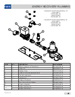
Page 55: ...fold Single point Tubing 05700 004 48 43 7 1 Vacuum Breaker 1 2 Brass 04820 003 06 13 8 1 Y Strainer 1 2 04730 217 01 10 9 1 Plug 1 2 Brass Pipe 04730 209 03 00 Complete ER Fill Plumbing Assembly L R 05700 004 41 53 Complete ER Fill Plumbing Assembly R L 05700 004 41 54 For areas with low ground water temperature a thermostatic mixing valve should be used Complete ER Fill Plumbing Assembly with Mi...

Page 56: ...cket 05700 004 41 58 6 2 Adapter 1 2 04730 011 59 53 7 1 Pressure Transducer 05945 004 17 01 8 1 Tee 1 2 x 1 2 x 1 4 Female 04730 411 25 01 9 1 Pressure Regulator 04820 100 04 07 10 1 Bracket ER Inlet L R 05700 004 41 55 1 Bracket ER Inlet R L 05700 004 41 56 Complete ER Inlet Plumbing Assembly L R with bracket 05700 004 41 62 without bracket 05700 004 41 64 Complete ER Inlet Plumbing Assembly R L...

Page 57: ...730 206 08 00 7 1 Rinse Injector L R 05700 003 76 82 1 Rinse Injector R L 05700 003 76 83 8 2 Adapter 1 2 04730 011 59 53 9 1 Fitting Comp 1 2 x 1 4 05700 004 36 74 10 1 Valve 1 2 04810 003 71 55 11 2 Elbow 1 2 04730 406 31 01 12 1 Union 1 2 04730 412 05 01 13 3 Plug 1 8 Brass 04730 209 07 37 14 1 Plug 1 4 Brass 04730 209 01 00 15 1 Turbo Rinse Injector 05700 004 32 61 Complete ER Rinse Plumbing A...

Page 58: ...07610 004 33 05 E 50 1 2 4 5 4 6 7 13 8 9 14 14 10 11 11 10 12 14 13 3 PARTS WASH SYSTEM 16 15 Mechanical Pump Seal 05330 002 34 22 ...

Page 59: ...3 72 37 9 1 Upper Wash Manifold 05700 003 73 66 10 1 Wash Arm Top right 05700 003 75 79 11 1 Wash Arm Top left 05700 003 75 80 12 12 Cap Threaded 04730 603 12 00 13 3 O ring Silicone 0 103 Dia 2 1 2 x 2 11 16 OD 05330 003 73 71 14 4 O ring Silicone 0 139 Dia 2 1 4 ID x 2 1 2 OD 05330 003 73 72 15 1 Wash Arm Bottom right 05700 004 27 43 16 1 Wash Arm Bottom left 05700 004 27 42 PUMP MOTOR ASSEMBLY ...

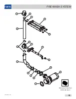
Page 60: ...07610 004 33 05 E 52 Mechanical Pump Seal 05330 002 34 22 PARTS PRE WASH SYSTEM 1 2 3 4 5 6 7 8 9 10 11 12 13 10 5 7 2 8 ...

Page 61: ...nifold 09515 003 77 22 8 2 O ring Silicone 0 139 Dia 2 1 4 ID x 2 1 2 OD 05330 003 73 72 9 1 Pre wash Arm 05700 003 75 79 10 4 Cap Threaded 04730 603 12 00 11 1 Pre wash Arm Lower 05700 003 80 96 12 1 Gasket Pump Discharge 05330 003 75 88 13 1 Pre wash Motor See Table Below PUMP MOTOR ASSEMBLY PART NUMBER Pre wash Pump 2HP 208 V 60 Hz 3 Phase 06105 003 76 12 Pre wash Pump 2HP 230 V 60 Hz 3 Phase 0...

Page 62: ...07610 004 33 05 E 54 PARTS RINSE SYSTEM 1 2 3 4 5 6 7 4 3 3 3 5 5 5 1 8 9 11 10 12 12 13 14 ...

Page 63: ...1 47 Hose Specify Length When Ordering 47 Hose Assembly Hose and Fittings 04720 004 19 81 05700 004 48 24 7 1 38 Hose Specify Length When Ordering 38 Hose Assembly Hose and Fittings 04720 004 19 81 05700 004 31 81 8 1 Coupling 1 2 to 3 4 04730 204 07 00 9 1 Elbow 3 4 Street Brass 04730 206 04 34 10 1 Plug 1 2 Brass 04730 209 03 00 11 1 Tee Reducing 3 4 to 1 2 04730 004 39 00 12 2 Lower Rinse Arm 0...

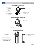
Page 64: ... 003 06 23 The PRV comes standard on ER units only NOTICE WATER TREATMENT OPTION Replacement Cartridge inspect at least every 6 months RSC 100 Scaltrol System 04730 003 05 76 Must be installed vertically The provided bracket is secured to the wall Observe proper inlet outlet water directions flow directions are molded into the top of the head Line pressure should be released before changing cartri...

Page 65: ... Rack Catch Left 05700 004 29 32 5 7 Rack Catch Right 05700 004 29 33 6 14 Bolt Shoulder 3 8 x 1 4 1 4 20 05306 004 29 34 7 1 Pawl Bar Weldment 05700 004 17 74 8 1 Rack Drive Guide 05700 004 29 36 9 2 Bolt Rack Drive Guide 1 4 20 x 3 4 Not Shown 05310 011 44 35 10 2 Lockwasher Rack Drive Guide Spring 1 4 Not Shown 05311 274 01 00 PARTS PAWL BAR 1 2 3 6 7 4 5 8 Complete Pawl Bar Assembly 05700 004 ...

Page 66: ...07610 004 33 05 E 58 PARTS RACK RAILS 1 3 4 2 2 2 3 4 4 4 6 6 5 4 4 7 8 8 7 8 4 9 8 10 11 10 11 8 10 10 10 11 11 11 8 8 8 RackStar 66 ...

Page 67: ...9 1 Paddle Switch Pre wash L R Paddle Switch Pre wash R L 05700 004 34 03 05700 004 34 06 10 9 Spacer Rack Guide 05700 011 71 44 11 9 Locknut 1 4 20 Hex with Nylon Insert 05310 374 01 00 Front Rack Rail Complete Assembly Everything below 05700 004 26 88 Rear Rack Rail Complete Assembly Everything below 05700 004 26 86 Pre wash Front Rack Rail Complete Assembly Everything below Left to Right Right ...

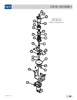
Page 68: ...07610 004 33 05 E 60 PARTS DRIVE ASSEMBLY 10 12 8 7 7 13 6 2 15 4 9 14 17 18 21 23 11 12 13 14 15 16 17 18 19 20 21 22 Drive Assembly 05700 004 29 95 doesn t include Item 17 1 3 5 ...

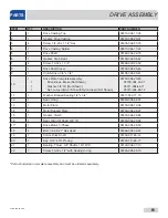
Page 69: ... 3 8 16 with Nylon Insert Not Shown 05700 004 29 49 05700 004 23 01 05311 004 48 71 05310 004 48 72 11 1 Washer Bonded Sealing 1 4 x 3 4 05311 002 77 79 12 1 Seal V ring 05330 004 52 14 13 1 Motor Plate 05700 004 19 38 14 1 Motor Support Plate 05700 004 26 97 15 1 Gasket Clutch 05330 004 28 88 16 1 Seal Viton Oil Shaft 3 4 ID 05330 004 29 06 17 1 Drive Motor 3 Phase 06105 004 29 53 18 4 Bolt 1 4 2...

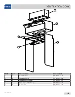
Page 70: ...WL ITEM QTY DESCRIPTION PART NUMBER 1 2 Ventilation Cowl 05700 004 34 01 2 2 Ventilation Scoop 05700 004 29 68 3 2 Ventilation Duct Adapter 05700 003 75 73 4 2 Damper Ventilation Scoop 05700 003 74 76 5 4 Curtain Hook 05700 003 17 98 3 2 1 4 5 ...

Page 71: ...ert the rod into the hole at the rear of the Ventilation Cowl 2 Insert the rod into the bracket at the front of the Ventilation Cowl 3 Gently lift the rod at the curtain cut out over and onto the curtain hook ensuring that the ends of the rod stay inserted in the holes This illustration depicts the Ventilation Cowl for a Left Unhooded Side loader 7 6 ORIENT THE CURTAIN SO THAT THE 3 CUTOUTS ARE LO...

Page 72: ...ector switch should be set to H for manual reset DRIVE MOTORS Overloads are specified for 3 phase units only For GE brand MT03 series overloads the process for setting is as follows Determine the FLA for the drive motor Set the overload at the closest setting without going over for the FLA of the motor The overload already compensates for the FLA and will have a setpoint that is 125 of the FLA Exa...

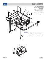
Page 73: ...to Right Unhooded Side loader Differences in parts for the 23 Right to Left and both directions of the 30 Side loaders are reflected in the parts list Order lengths of hose or conduit by mea suring the lengths in the field and adding an additional 1 to ensure any custom cut lengths are accounted for PARTS SIDE LOADERS NOTICE ...

Page 74: ...cts a 23 Left to Right Unhooded Side loader Differences in parts for the 23 Right to Left and both directions of the 30 Side loaders are reflected in the parts list Order lengths of hose or conduit by mea suring the lengths in the field and adding an additional 1 to ensure any custom cut lengths are accounted for NOTICE ...

Page 75: ...h Assembly 05700 004 53 51 8 1 Gutter Pawl Bar 05700 021 66 86 9 1 Guide Block Bottom slotted 05700 011 69 50 10 1 Guide Block Top slotted 05700 011 69 49 11 1 Gasket Drive Gutter 05330 011 68 55 12 1 Strainer 05700 021 85 10 13 1 Drain Assembly Side loader 05700 004 38 17 14 1 Bracket Loader Pawl Bar Support 05700 003 87 39 15 16 Washer 1 4 05311 174 01 00 16 2 Roller 05700 011 68 16 17 2 Roller ...

Page 76: ...ut 3 8 16 with Nylon Insert 05310 011 72 55 5 3 Bolt 3 8 16 x 1 3 4 Hex 05306 011 36 94 6 6 Spacer Pawl Bar Dog 05700 011 71 45 7 2 Screw 1 4 20 x 1 Hex 05305 274 27 00 8 2 Locknut 1 4 20 Hex with Nylon Insert 05310 374 01 00 9 2 Drive Link 05700 004 46 82 10 4 Lockwasher Spring 05311 274 01 00 11 4 Screw 1 4 20 x 7 8 05305 274 05 00 PARTS SIDE LOADER DRIVE LINKAGE 6 1 4 3 5 2 7 8 9 10 11 ...

Page 77: ... 4 04820 011 87 39 6 1 Nipple 3 4 Black Iron 4 Long 04730 907 02 34 7 1 Y strainer Steam 3 4 04730 217 01 32 8 1 Gate Valve Steam 3 4 04820 100 19 00 9 1 Steam Condensate Assembly L R 05700 004 46 56 1 Steam Condensate Assembly R L 05700 004 46 33 Complete Steam Coil Assembly L R 05700 004 44 82 Complete Steam Coil Assembly R L 05700 004 46 30 PARTS STEAM COIL 1 2 9 4 7 6 5 4 3 8 Complete Steam In...

Page 78: ... V 3 Phase 04540 004 29 77 18 kW 70 F Rise 460 V 3 Phase 04540 004 30 77 18 kW 70 F Rise 600 V 3 Phase 04540 004 55 87 27 kW Energy Recovery 208 V 3 Phase 04540 004 41 68 27 kW Energy Recovery 230 V 3 Phase 04540 004 41 69 27 kW Energy Recovery 460 V 3 Phase 04540 004 41 70 27 kW Energy Recovery 600 V 3 Phase 04540 004 55 88 ITEM QTY DESCRIPTION PART NUMBER 1 1 Booster Heater See Chart Below For B...

Page 79: ...ART NUMBER 12 kW 40 F Rise 208 V 3 Phase 05700 004 48 38 12 kW 40 F Rise 230 V 3 Phase 05700 004 48 41 12 kW 40 F Rise 460 V 3 Phase 05700 004 48 39 12 kW 40 F Rise 600 V 3 Phase 05700 004 91 88 17 2 kW 70 F Rise 208 V 3 Phase 05700 004 48 31 18 kW 70 F Rise 230 V 3 Phase 05700 004 48 32 18 kW 70 F Rise 460 V 3 Phase 05700 004 48 33 18 kW 70 F Rise 600 V 3 Phase 05700 004 91 90 27 kW Energy Recove...

Page 80: ...el RackStar 44 05700 004 30 44 5 1 Adjustable Foot 05340 011 71 74 6 1 Right Dress Panel L R 05700 004 30 59 Left Dress Panel R L 05700 004 31 92 7 1 Pre wash Hood Dress Panel 05700 004 30 08 8 1 Front Dress Panel RackStar 66 05700 004 34 48 9 1 Drain Valve 04820 111 71 46 10 1 Drain Handle Complete Assembly 05700 004 31 89 1 Drain Handle Only 05700 004 31 90 11 1 Support Bracket Drain Hose 05700 ...

Page 81: ...embly HH 05700 004 80 04 05700 004 81 12 3 4 Bearing Flanged Sleeve 03120 004 39 92 4 2 Door Seal 09330 004 17 41 5 10 Screw 10 32 x 1 2 05305 011 44 51 6 1 Door Assembly Pre wash L R Door Assembly Pre wash R L Door Assembly Pre wash L R HH Door Assembly Pre wash R L HH 05700 004 75 90 05700 004 75 93 05700 004 79 78 05700 004 76 94 1 2 4 3 Door Switch 05930 002 36 80 5 Not Shown ...

Page 82: ...07610 004 33 05 E 74 PARTS ENERGY RECOVERY SYSTEM Complete Energy Recovery System Assembly L R 05700 004 39 68 R L 05700 004 40 13 L R HH 05700 004 68 92 R L HH 05700 004 69 04 ...

Page 83: ...p 05700 004 36 73 13 1 Collar Vent Scoop 05700 004 36 71 14 1 Curtain 20 1 2 x 19 Curtain HH 20 1 2 x 29 3 4 08415 002 14 41 08415 004 49 64 15 1 Baffle Vent Cowl 05700 002 11 47 16 5 Screw 1 4 20 x 5 8 Hex 05305 274 24 00 17 10 Screw 10 32 x 1 2 05305 011 39 36 18 1 Drip Tray 05700 004 42 09 19 3 Locknut 1 4 20 Low Profile with Nylon Insert 05310 374 02 00 20 2 Bushing 3 4 to 1 2 Hex Brass 04730 ...

Page 84: ... 05700 004 32 75 Strainer Wash Tank 05700 004 29 02 Strainer Pre wash 05700 004 37 61 PARTS MISCELLANEOUS OPTIONS Miscellaneous Parts Options Striker Table Limit Switch Option 05700 002 88 07 Whisker Table Limit Switch Option 05700 002 06 83 Pre wash Connecting Rod 05700 004 56 16 ...

Page 85: ...put Assignments I1 Wash I2 Cycle I3 Float I4 Rinse I5 Door Chemicals BLK DC RTN RED 24 VDC WHT BLK DC RTN VDCOUT CORRESPONDING CONNECTOR GOING TO DISPLAYPCB B L K B L K R E D W H T B L K G R N LOGIC INPUT VDCOUT T3 GRN BLK K 2 K 3 K 4 K 5 K 6 K 7 K 8 K 9 K 10 K 11 K 12 Interconnectcableis Belden 9745 060U500 3 twisted pairs ConnectionDiagramfor IO Module DC RTN 1 2 3 4 5 5 6 6 1 2 3 4 PAIR1 PAIR2 ...

Page 86: ...L1 L2 N Input Assignments I1 Wash I2 Cycle I3 Float I4 Rinse I5 Chemicals BLK DC RTN RED 24 VDC WHT BLK DC RTN 24 VDC CORRESPONDING CONNECTOR TO DISPLAY PCB PN 05945 004 36 33 B L K B L K R E D W H T B L K G R N LOGIC INPUT 4 5 VDC OUT T3 Booster RED BLU GRN BLK K 2 K 3 K 4 K 5 K 6 K 7 K 8 K 9 K 10 K 11 K 12 Interconnect cable is Belden 9745 060U500 3 twisted pairs Connection Diagram for IO Module...

Page 87: ...L1 L2 N Input Assignments I1 Wash I2 Cycle I3 Float I4 Rinse I5 Chemicals BLK DC RTN RED 24 VDC WHT BLK DC RTN 24 VDC CORRESPONDING CONNECTOR TO DISPLAY PCB PN 05945 004 36 33 B L K B L K R E D W H T B L K G R N LOGIC INPUT 4 5 VDC OUT T3 Booster RED BLU GRN BLK K 2 K 3 K 4 K 5 K 6 K 7 K 8 K 9 K 10 K 11 K 12 Interconnect cable is Belden 9745 060U500 3 twisted pairs Connection Diagram for IO Module...

Page 88: ...nput Assignments I1 Wash I2 Cycle I3 Float I4 Rinse I5 Chemicals BLK DC RTN RED 24 VDC WHT BLK DC RTN 24 VDC CORRESPONDING CONNECTOR TO DISPLAY PCB PN 05945 004 36 33 B L K B L K R E D W H T B L K G R N LOGIC INPUT 4 5 VDC OUT T3 Booster RED BLU GRN BLK K 2 K 3 K 4 K 5 K 6 K 7 K 8 K 9 K 10 K 11 K 12 Interconnect cable is Belden 9745 060U500 3 twisted pairs Connection Diagram for IO Module PN 05945...

Page 89: ...07610 004 33 05 E 81 SCHEMATICS SIDE LOADER ...

Page 90: ...3 05 E This page can be copied and the display templates cut out Lay the cut out over the display and use the Up arrow Down arrow and Select Buttons to locate the hidden programming buttons ADDENDUM DISPLAY TEMPLATE ...

Page 91: ......

Page 92: ...Jackson WWS Inc 6209 N US Hwy 25E Gray KY 40734 USA 1 888 800 5672 www jacksonwws com RackStar Manual 07610 004 33 05 E ...

Reviews: