

Installation Instructions
MODEL LS-HC
Limit -Stat™
Single Stage (1H/1C)
Non-Programmable Thermostat
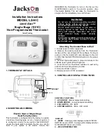
1. THERMOSTAT DETAILS
2. MOUNTING AND WIRING
Electric Heat or Single Stage
Heat Pump Systems
This thermostat is configured from the factory to operate
a heat/cool, fossil fuel (gas, oil, etc.), forced air system. It
is configured correctly for any system that DOES NOT
require the thermostat to energize the fan on a call for
heat. If your system is an electric furnace that
REQUIRES the thermostat to turn on the fan set the
ELECTRIC/GAS switch to the electric position. (See
Thermostat Details) This will allow the thermostat to
energize the fan immediately on a call for heat.
WARNING
Do not use on circuits exceeding specified
voltage. Higher voltage will damage control
and could cause shock or fire hazard.
Do not short out terminals on gas valve or
primary control to test. Short or incorrect
wiring will damage thermostat and could
cause personal injury and/or property
damage.
Thermostat installation and all components of
the system shall confirm to Class II circuits
per the NEC code.
Patent Pending
Attaching Thermostat Base to Wall
1. Disrupt power to HVAC equipment.
2. Remove the packing material from the thermostat.
Gently pull the cover straight off the subbase. Forcing or
prying on the thermostat will cause damage to the unit.
Confirm that the ELECTRIC/GAS Switch is in the proper
position.
3. Connect thermostat wires to proper terminals on the
subbase (see Typical Wiring Diagrams).
4. Level and mount thermostat subbase to wall using
anchors and mounting screws provided.
5. Snap cover back in place.
6. Reapply power to HVAC equipment.
3. CONTROL AND DISPLAY FUNCTIONS
CONTROL FUNCTIONS
1 - UP ARROW
– Raises temperature setting.
2 - DOWN ARROW
– Lowers temperature setting.
3 - FAN SWITCH
– ON, AUTO
4 - SYSTEM SWITCH
– COOL, OFF, HEAT
DISPLAY
.
5 – MODE
– Heating symbol displayed when SYSTEM
SWITCH is set to HEAT. Cooling symbol displayed when
SYSTEM SWITCH is set to COOL.
6 – SPACE TEMPERATURE
Wire to furnace
‘W’ Terminal
LIMITER


