background image


Note: 

features of this system can be substantially modified by programming 

during installation. The installer should instruct the users how to operate and test 

the system. 

2  Indicators 


The alarm system’s status is indicated  on the keypad. There can be multiple 

keypads in the system and in such a case all keypads will have identical functions. 

A keypad’s LED indicators and display inform the user about the conditions of the 

system. 


LED indicators: 


Alarm: 

alarm triggered by an intruder, smoke, gas etc


Tamper: 

opened cover, damaged detector, excessive 

number of attempts to enter code, etc.  

Fault: 

power loss, lost communication with a detector 

etc., (view details by pressing 

N

Battery: 

battery of the device specified on the display is 

low. See battery replacement section. 

  information received from a wireless item or wireless 

communication of the keypad in progress   

Armed: 

continues  = armed, slow blinking  = exit delay, 

fast blinking = entrance delay 

Power: 

continues  = AC power & back up battery O.K., 

blinking  = failure (AC or back up battery), off  = control 

panel is not powered 
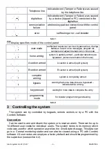
 

88

 display specifies event source: 


wireless 

detector 12  

indicated event (Alarm, Tamper, Failure or 

Battery) was caused by detector number 12  


wired zone 2 

indicated event (Alarm, Tamper, Failure or 

Battery) was caused by wired zone number 2 


wireless 

controller 3 

indicated event was caused by wireless 

controller (remote control, keypad, Panic button)  

number 3 


Control panel  indicated event (Tamper or Failure) was caused 

by the control panel  


Wireless siren 

indicated event (Tamper, Failure or Battery)  

was caused by the outdoor wireless siren 


Sub control 

panel 

indicated event (Alarm, Tamper, Failure or 

Battery) was caused by the sub control panel  

Alarm system JA-63 „Profi“ 

- 3 - 

MGK51504 

Summary of Contents for Profi

Page 1: ...JA 63 Profi User manual...

Page 2: ...equent period of two 2 years Should your Product need warranty service please return it to the dealer from whom it was purchased Conditions 1 The warranty is valid only if the original receipt issued...

Page 3: ...on information received from a wireless item or wireless communication of the keypad in progress Armed continues armed slow blinking exit delay fast blinking entrance delay Power continues AC power ba...

Page 4: ...rmed B section is armed split system complete arming system is completely armed bypass warning that some detectors are bypassed indicated while arming key pressed waiting for more data to complete the...

Page 5: ...ill beep once and the exit delay countdown will start ARMED indicator will flash during exit delay you should leave the protected area within the duration of the exit delay If there are 4 beeps while...

Page 6: ...telephone line depends on installation settings Panic alarm can be triggered On the keypad press the panic key and then enter your access code On the remote control RC 4x press the and buttons simulta...

Page 7: ...also be viewed on the keypad by entering F 4 will show the last recorded alarm or failure Press key 4 multiple times to go deeper in to the memory 3 8 Split system arming The system can be split by th...

Page 8: ...ypad or by SMS messages the control panel must be equipped with GSM communicator for this feature Installer can program that this feature will work only when the entry is followed by a user code 4 Use...

Page 9: ...eleted by F 6 1234 03 0000 Notes You can program new codes only when the system is disarmed The supervisor should record the codes to the table on last page of this manual it should be kept hidden in...

Page 10: ...tomatic arming and disarming can be overridden manually anytime by a user code or a remote control If the control panel is in the requested arming mode before the action time the programmed action wil...

Page 11: ...ith a JA 60GSM communicator please look at the JA 60GSM user manual for details about user s setting 5 2 JA 65X Telephone communicator If the control panel is equipped with a JA 65X telephone communic...

Page 12: ...r mode Enter F0 master code to switch to the user mode U will be indicated on the keypad No alarm can be triggered while in the user mode and any triggering of a detector a remote control or a panic b...

Page 13: ...e battery life Recommendations the system should be annually inspected by a professional installer The control panel and the outdoor siren back up batteries should be replaced with new ones after 5 ye...

Page 14: ...0 Master code supervisor 1 2 3 4 5 6 7 8 9 10 11 12 13 14 c1 c2 c3 c4 c5 c6 c7 c8 Telephone communicator setting memory calling to tel number notes 1 2 3 4 5 Pager Timers exit delay sec entrance delay...

Page 15: ...in the house detectors type reaction section A B S WIRELESS DETECTORS 1 2 3 4 5 6 7 8 9 10 11 12 13 14 15 16 WIRED INPUTS 1 2 3 4 I instant D delayed F fire P panic T tamper N next delayed Alarm syst...

Page 16: ...Notes Alarm system JA 63 Profi 16 MGK51504...

Reviews: