


By means of the computer electronic management it is pos-
sible to actuate in fast sequence both primary functions such
as metering computation and injection advance and sec-
ondary ones, only necessary in special conditions.
Metering and advance, actuated three times per every crank-
shaft revolution, are selectively calculated cylinder by cylinder
at every injection, while secondary functions as the acceler-
ation management or heating element on fuel filter activation
are controlled only when necessary.
Moreover the electronic unit is programmed to carry out
continuous checks on presence and consistency of the sig-
nals originated from the system sensors, to timely notify the
onset of faults or actuate the exclusion of a datum whenev-
er its content is in contrast with the logic sequence of the
events occurred up to that moment.
Run up
Immediately after having electrically powered up the system
(key is in position ON), the central unit
before setting on
the cranking motor
, transfers into the main working mem-
ory data which have characterised the best engine opera-
tion during the previous operation period; they represent
the progressive engine ageing and they progressively evolve
with usage.
By using this function engine management is always opti-
mized even from the first operation stages, indipendently
from the usage conditions of the engine.
The data transferred after the run-up are those stored after
the last engine stop during the “after run” function.
Starting
It is the management stage of the engine functions charac-
terised by the adotpion of useful strategies to a fast reaching
of the endothermic engine functions.
Among the restrained signals the most evident is the recog-
nition of the throttle position that does not require to be
operated until the starting procedure is concluded.
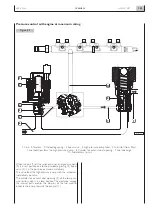
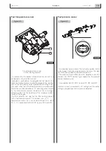
Metering and fuel injection
It is carried out by the span of time of the injectors electric
control fed by the pressurized fuel in the accumulator time
sharing.
Fuel pressure in the time sharing apparatus is made to
change according to the performance goals required from
the engine.
The primary datum of the amount of fuel to be injected is
calculated according to the information of:
-
Throttle position
-
Engine number of RPM
This datum is adjusted furtherly according to the data of:
-
Comburent air pressure and temperature.
-
Fuel temperature.
-
Engine coolant temperature.
It may be modified by linearization for acceleration gradient,
the minimum RPM, to avoid runaway speed rate or to con-
trol limit condition of engine operation.
The span of time of the electro-injector control which sets
the real quantity injected is, moreover, related to the fuel
pressure datum detected on the time sharing apparatus and
the accumulator voltage.
Only in the case of anomalies which entail serious damages
for the engine, injection time zeroing is reached.
Injection advance management
It is obtained by changing in the span of time of one revolu-
tion of the crankshaft the instant of the electric control
beginning of the electro-injectors.
The values actuated may vary from one injection to the next
one and in the same way as for the metering varied among
the cylinders.
The parameters affecting the injection advance are:
-
Throttle position
-
Engine RPM
-
Comburent air temperature and pressure.
-
Fuel temperature.
-
Coolant temperature.
The values are determined experimentally in order to obtain
the best performance and at the same time complying with
containment goals on acoustic and fumes emissions.
A further dynamic adjustment during the acceleration phase
gives to the engine a greater static torque.
The information to check the actuated value obtained in
“loop” is provided by the electro-injector solenoid imped-
ance change.
N60 ENT M37
OVERVIEW
1.49
APRIL 2004
SYSTEM FUNCTIONS
Summary of Contents for N60 ENT M37
Page 4: ...N60 ENT M37 IV APRIL 2004 ...
Page 52: ...N60 ENT M37 OVERVIEW 1 52 APRIL 2004 ...
Page 54: ...N60 ENT M37 TECHNICAL DATA 2 54 APRIL 2004 ...
Page 60: ...N60 ENT M37 TECHNICAL DATA 2 60 APRIL 2004 ...
Page 62: ...N60 ENT M37 ELECTRICAL EQUIPMENT 3 62 APRIL 2004 ...
Page 92: ...N60 ENT M37 DIAGNOSTICS 4 92 APRIL 2004 ...
Page 116: ...N60 ENT M37 DIAGNOSTICS 4 116 APRIL 2004 ...
Page 118: ...N60 ENT M37 MAINTENANCE 5 118 APRIL 2004 ...
Page 122: ...N60 ENT M37 MAINTENANCE 5 122 APRIL 2004 ...
Page 124: ...N60 ENT M37 SERVICING OPERATIONS ON INSTALLED ENGINE 6 124 APRIL 2004 ...
Page 139: ...SECTION 7 TOOLS Page TOOLS 141 N60 ENT M37 TOOLS 7 139 APRIL 2004 ...
Page 140: ...N60 ENT M37 TOOLS 7 140 APRIL 2004 ...
Page 146: ...N60 ENT M37 TOOLS 7 146 APRIL 2004 ...
Page 156: ...APRIL 2004 OVERHAUL 8 156 N60 ENT M37 ...
Page 164: ...APRIL 2004 OVERHAUL 8 164 N60 ENT M37 ...
Page 181: ...OVERHAUL APRIL 2004 N60 ENT M37 8 181 ...
Page 188: ...N60 ENT M37 OVERHAUL 8 188 APRIL 2004 ...
Page 190: ...N60 ENT M37 SAFETY PRESCRIPTIONS 9 190 APRIL 2004 ...
Page 193: ......