References
of Load Communication Interfaces
Copyright ©ITECH Electronic Co., Ltd.
44
⚫
The interface receives the command MsgID=TRIGGER USBTMC and
conveys the TRIGGER command to the functional layer.
The functions of load USB488 device are as follows:
⚫
Capable to read all common SCPI commands.
⚫
SR1 enabled.
⚫
RL1 enabled.
⚫
DT1 enabled.
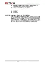
5.3 GPIB interface (Only for IT8912E(G))
Firstly, connect load GPIB interface and computer GPIB card through IEEE488
bus and ensure sufficient contact. Tighten them with screws. Set address. Load
address range: 0-31. Press
[Shift]
+ numeric key 8 (System) to enter system
menu functions. Press Left/Right key to find Communication. Select GPIB and
set address. Input address and press
[Enter]
for confirmation. The load works
by setting GPIB address on front board. GPIB address is saved in NVM.

