Itec SDR-2716-A Manual Download Page 3

www.itec-audio.com     

3

MICROPHONES

ITEC RADIO MICROPHONE SYSTEMS
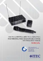
1 m

1 m

1 m

1 m

1.3. General assembly instructions 

1.3.1. Positioning of the receiver

For proper operation, the receiver should be 
positioned as high as possible, at least, however, 
1 m above the fl oor. The clearance from walls and 
metal surfaces should also be at least 1 m. For 
proper operation, the transmitter (microphone) 
must not be positioned closer than 1 m from the 
receiver. Proximity to sources of interference, 
such as e.g.: motors, fl uorescent lamps, spot-
lights, cars, mobile telephones, computers etc. 
should also be avoided.
Especially for WiFi routers a distance of a few 
meters is recommended!

1.3.2. Assembly of the receivers in the 19“ rack

The ITEC SDR 2716-A is suitable for installation in 19 „racks.
There are two different sets of mounting brackets available.

Installation of one receiver with mounting bracket set FB 71-A

Installation of two receivers with mounting bracket set FB 72-A

In case of rack installation, the use of external antennas is recommended.

Summary of Contents for SDR-2716-A

Page 1: ...MICROPHONE SYSTEM VHF FREQUENCY RANGE MANUAL ITEC Tontechnik und Industrieelektronik GesmbH 8200 Gleisdorf La nitzthal 300 Austria Europe WM 716 A A W W WT T T 7 71 16 6 A A S SD DR 716 A SDR 2716 A P...

Page 2: ...ble see point 5 frequency list 1 Introduction 1 1 System components Overview Transmitter WM 716 A Hand held microphone electret condenser capsule Operation with 2 batteries 1 5V AA or optional with 2...

Page 3: ...han 1 m from the receiver Proximity to sources of interference such as e g motors fluorescent lamps spot lights cars mobile telephones computers etc should also be avoided Especially for WiFi routers...

Page 4: ...djustment Elements on the back 7 ANT A ANT B TNC sockets for connecting the supplied rod antennas or ext antennas 8 DC IN Socket for connecting the supplied power adapter 9 MIC Balanced microphone out...

Page 5: ...receiver is made using the Channel buttons To avoid unintentional ad justment the buttons are normally locked To unlock press both buttons simultaneously for about 5 seconds until the display flashes...

Page 6: ...tment There are two frequency ranges EUV232 and EUV243 with 8 adjustable channels each see point 5 Frequency list The range is defined by the respective variant and can not be changed The channel sett...

Page 7: ...red for a long time leading to corrosion and destruction of the battery contacts and the PCB Use high quality alkaline batteries these also allow a longer operating time Regargeable Batteries Alternat...

Page 8: ...tion of the battery contacts and the PCB Use high quality alkaline batteries these also allow a longer operating time Regargeable Batteries Alternatively the wireless microphone WM 716 A can also be o...

Page 9: ...o a wall outlet with the associated 230VAC 12VDC power adapter Charging indication Flashing red charging station is free or batteries are defective or contact is not correct Solid red battery is charg...

Page 10: ...25 2 10 243 700 3 11 234 625 3 11 244 600 4 12 235 675 4 12 246 300 5 13 236 575 5 13 247 100 6 14 237 325 6 14 247 500 7 15 237 775 7 15 248 600 8 16 237 925 8 16 249 900 Hereby ITEC Tontechnik und I...

Page 11: ...ED 2014 53 EU Normen Generic standards EMC EN 301 489 1 V2 2 0 2017 EN 301 489 9 V2 1 1 2017 Radio Spectrum EN 300 422 1 V 2 1 2 2017 Safety IEC 62368 1 2014 COR1 2015 EN 62368 1 2014 A11 2017 ING WER...

Page 12: ...3 x 60 x 30 mm Weight 61 g SDR 2716 A DIVERSITY RECEIVER 19 Power supply 12 V DC PSU 230 V AC 12 V DC included Dimensions weight 200 x 47 x 180 mm 1 2 19 1 HE Weight 0 7 kg SDR 716 RECEIVER MODULE Pow...

Reviews: