background image

41

Maintenance

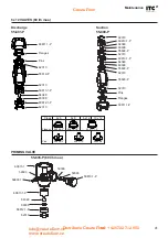
6 x 12 VALVES (60 l/h max.)

PRIMING VALVE

55-835-P (60 l/h max.)

Discharge
55-801-P

Suction
55-800-P

Pipes

Flanges

55826-P

60878.1-P

60877.1-P

Pins

55825-P

55827-P

55829-P

4 x 6

6 x 8

6 x 12

10 x 12

60811.1-P

62310

60813.1-P

64348

60308

55822-P

62310
60813.1-P

64348

60308

55822-P
62310

55820-P

62310
Pins

Flanges

60811.1-P

Flanges

Pins

62310

55819-P

62310

62310

60815.1

59306

59303

59810.1-P

59303

59800.1

60813.1-P

64348

60308

60812.1-P

62310

60813.1-P
64348

60308

60812.1-P

Create Flow

[email protected] 
www.createflow.cz

Distribuce Create Flow

tel: +420 722 712 652

Summary of Contents for DOSmart AC F30-D50

Page 1: ...ENGLISH Create Flow info createflow cz www createflow cz Distribuce Create Flow tel 420 722 712 652 ...

Page 2: ...RIES 14 4 4 1 Diaphragm leakage detector 14 4 4 2 Pressure sensor 14 4 4 3 Pulse output isolator 14 5 OPERATION 15 5 1 OPERATING MODES 17 5 1 1 Manual mode 17 5 1 2 Proportional mode 17 5 1 3 Analogue mode 19 5 1 4 Batch dosing mode 20 5 1 5 Special functions 23 5 2 CONFIGURATION 24 5 2 1 Pump calibration 24 5 2 2 Dosing mode 24 5 2 3 Configuration 26 5 2 4 Inputs outputs 30 Create Flow info creat...

Page 3: ... Wiring 45 CE DECLARATION OF CONFORMITY 47 WARRANTY 47 To avoid personal injury risks and damage to the environment and to ensure proper equipment operation personnel responsible for installing commissioning and maintaining the equipment must follow the instructions in this manual with special attention to the detailed recommendations and warnings The specific instructions for the use of the chemi...

Page 4: ...by keyboard of the flow rate to be dosed Analogue dosing proportional to a 0 4 20 mA analogue signal Proportional to flow rate dosing proportional to a water flow rate Proportional by pulses stroke frequency proportional to input pulses Batch control by volume dosing a given volume Manual remote or timed activation Batch control by time dosing for a given time Manual remote or timed activation Mod...

Page 5: ...d and stored without damage provided this takes place in dry ventilated spaces away from heat sources Included in the packaging are DOSmart AC dosing pump Instruction manual Connection accessories for 4x6 6x8 6x12 10x12 conduit Create Flow info createflow cz www createflow cz Distribuce Create Flow tel 420 722 712 652 ...

Page 6: ...ion head priming with empty head m 2 2 2 3 3 3 3 Max viscosity std valve and minimum DN pipe mPa s 100 10 200 100 200 200 100 Max viscosity M valve with spring and DN15 pipe mPa s 3000 3000 3000 3000 2100 2000 600 Max viscosity M valve SS1 with spring and DN15 pipe mPa s 3000 3000 3000 3000 3000 3000 1800 Max viscosity M valve SS2 with spring and DN15 pipe mPa s 3000 3000 3000 3000 3000 3000 1800 ...

Page 7: ... alarm Leakage detector input Flow detector input Pressure sensor input RS 485 ModBus serial port 4 20 mA log and monitoring output Log output monitoring and control of second pulse pump Alarm output relay Level alarm output relay DIMENSIONS 267 183 83 253 248 296 172 143 Create Flow info createflow cz www createflow cz Distribuce Create Flow tel 420 722 712 652 ...

Page 8: ...4 12 18 l h Bar 6 4 2 0 F51 D50 l h Bar 39 40 41 42 43 44 3 2 1 0 F41 D69 8 9 7 10 11 12 13 14 l h Bar 6 8 6 4 2 0 F30 D50 2 3 1 4 5 l h Bar 0 10 8 6 4 2 0 12 14 16 S50 D50 5 6 4 7 8 9 l h Bar 3 10 8 6 4 2 0 12 F50 D50 23 24 25 26 27 28 29 l h Bar 0 F31 D50 2 4 Create Flow info createflow cz www createflow cz Distribuce Create Flow tel 420 722 712 652 ...

Page 9: ...on of air Fix the pump on a rigid horizontal surface Provide enough space to comfortably perform basic maintenance and facilitate installation and removal Fix the pump to the chosen flat surface using 4 screws See drawing 81 234 129 5 8 81 234 129 Create Flow info createflow cz www createflow cz Distribuce Create Flow tel 420 722 712 652 ...

Page 10: ... C NO 5 V H L 37 38 39 40 41 42 43 44 45 46 I N N O NC CN O NC C P 1 2 ENCODER Inputs Outputs External quick connectors Flow Rupture Pressure Red Blue Yellow ENCODER 1 2 3 4 5 6 7 8 10 11 12 FLOW LEAKAGE PRESSURE VENTILATION RS 485 4 20 mA PULSE PULSE ALM LEVEL ALM REMOTE LEVEL 1 LEVEL 2 4 20 mA 4 20 mA ITC controllers Pulse input ITC flowmeter Remote activation Level sensors Brown Brown Brown Bla...

Page 11: ...age free contact 19 Level sensor 1 Voltage free contact 21 Level sensor 2 Voltage free contact 22 Common level sensor Voltage free contact Outputs 33 RS 485 5 Vdc 34 RS 485 H B 35 RS 485 L A 36 RS 485 37 4 20 mA monitor output Not isolated 38 4 20 mA monitor output Not isolated 39 Monitor pulse output Signal Not isolated 40 Monitor pulse output Not isolated 41 Level alarm 2 output NO 42 Level alar...

Page 12: ... liquid leakage from the cylinder s vent drain orifice in a proper container 6 Priming and drain valve built into the pump 7 Pressure relief valve Install a pressure relief valve in a bypass as close as possible to the pump in order to protect the pump and the installation from possible overpressure This bypass should pipe the liquid to a safe place 8 Pulse dampener 9 Pressure gauge 10 Pressure ma...

Page 13: ... 6 5 ft Air in suction Siphon DISCHARGE SUCTION L Ø L Ø h p h PIPE SIZE Øint L 2 m L 5 m 4 4 4 6 13 10 60 13 15 40 20 60 Q max l h PIPE SIZE Øint L 2 m L 5 m 4 4 4 6 13 13 10 60 40 15 60 Q max l h Q max l h Create Flow info createflow cz www createflow cz Distribuce Create Flow tel 420 722 712 652 ...

Page 14: ...9 063 P 4 4 2 Pressure sensor The pressure sensor protects the pump from working in overpressure conditions when the pressure alarm is activated Connect the 4 20 mA 10 bar pressure sensor Ref 18705 as shown in the drawing 18705 1 24 2 1 24 10 11 12 PRESSURE 2 4 4 3 Pulse output isolator 38 39 40 41 27 28 29 31 32 33 34 The pulse output isolator allows any device to be securely connected to a pulse...

Page 15: ...ying the speed of the motor and depending on the operating mode selected in the Control Unit the equipment will regulate the flow to the desired value with a maximum variation of 1 3000 EQUIPMENT DESCRIPTION LCD screen Keyboard Exit without confirming Validate Run Stop Increase decrease value Scroll left Scroll right test ESC ENT Inputs outputs Control unit B A C D F Injection valve Suction valve ...

Page 16: ...pulse Manual Level 1 Pump calibration Proportional Level 2 Dosing Mode Analogue Flow rate Standard ST Batch Leakage Pressure Slow Suction 1 SS1 Slow Suction 2 SS2 Set Up In Out Dosing pump Pressure Input Units Flow detector Inputs Real time Flowmeter Pulse output Counters Lock code Outputs 4 20 mA out Info Unit ModBus Monitor motor Cycles min ON OFF Monitor Alarm Configuration Mode 25 0 25 0 25 0 ...

Page 17: ...portional Analog Batch l h M o 0 0 0 0 0 0 off l l h M 3 1 4 4 ENT ENT ENT Increase decrease flow Start stop the pump The pump will start if the Remote Activation input is activated Proportional to a pulse input from a flowmeter 1 X Y for low frequency pulses 0 005 30 Hz 2 ppm for high frequency flowmeters 1 300 Hz l h 0 0 0 0 0 0 MODE MODE Manual Analog Batch Proportional l h 10 m3 h o 0 0 0 0 0 ...

Page 18: ...e the Configuration Setup section l h 60 0 l 2 5 3 6 6 25 12150 l h 30 m3 h l 6 2 8 9 15 5 Select the number of pump cycles Change by pressing and validate by pressing ENT Select pump speed in Change by pressing and confirm by pressing ENT For Y 1 Q must be set at less than 50 Select the maximum number of pulses in memory Change by pressing and confirm by pressing ENT Proportionality value in or p...

Page 19: ...al Proportional Batch Analog 1 l h 00mA o 0 0 0 0 0 0 5 1 3 1 Analogue mode configuration ANALOG INPUT INPUT 16 0 mA 100 00 0 mA 067 ANALOG INPUT INPUT 16 0 mA 100 00 0 mA 067 25 0 25 0 Select mA input for the first point Change by pressing and confirm by pressing ENT Select ON to perform proportional dosing with a volume limit The pump will stop when it reaches the ENT maximum volume to be dosed ...

Page 20: ...eed of the pump can be defined in ANALOG INPUT INPUT 16 0 mA 100 067 ANALOG INPUT 4 mA 000 SPAN 20 mA 100 l h 2 8 0mA l 2 5 3 6 ENT Start stop the pump The pump will start if the Remote Activation input is activated 100 41 22 0 mA 100 41 22 0 mA 100 41 22 0 mA 100 41 22 0 mA ENT ENT l h 0 0 0 0 0 0 MODE x2 MODE Manual Proportional Analog ModBus Batch 01 600 l 00 000 l o 0 0 0 0 0 0 6 25 25 0 Selec...

Page 21: ...Stroke Start Ext BATCH MODE Flow 000 Stop Stroke Start Time BATCH MODE Stop Stroke Start Man Flow 050 BATCH MODE Start Man Flow 050 Stop Stroke ENT ENT 5 1 4 2 Select stroke frequency in flow 5 1 4 3 Select stop mode BATCH MODE Start Man Flow 050 Stop 000050 St Volume 208 15ml Manual start the pump by pressing ENT Change by pressing and confirm by pressing ENT Change by pressing and confirm by pre...

Page 22: ...0 7 3 00 00 10 00 00 00 l 5 0 7 3 01 379 00 000 l l 00 10 00 l 5 0 7 3 00 00 10 00 00 00 00 10 00 l 5 0 7 3 Volume to be dosed Volume counter Execution time Time counter Initial frequency Volume to be dosed Volume counter Initial frequency Execution time Time counter BATCH MODE Start Man Flow 050 Stop 00 00 10 Volume 34 722 ml Change by pressing and confirm by pressing ENT Create Flow info createf...

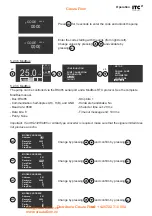
Page 23: ...y via the ENT key After stopping the pump manually via the keypad it is necessary to reset the Remote Input open and close to start the pump again remotely 5 1 5 2 Priming function test By pressing for 3 seconds in manual mode to start the pump at maximum speed The pump will continue to run only when is pressed This feature allows a quick test of the unit and is an aid in priming the pump Create F...

Page 24: ...s via a product suction test of a given duration For a correct calibration a test duration of at least 60 seconds must be entered The pump will automatically start during the time of the test Once the test is finished the suction volume must be entered With this result the equipment will recalculate the dosing flow l h 0 0 0 0 0 0 MODE 25 0 PUMP CALIBRATION 000 Test Time ST Dos Mode 100 Flow PUMP ...

Page 25: ...is also reduced to 50 to avoid overpressure in long deliveries In this mode the flow is reduced to 50 5 2 2 1 Low pulsation standard The Standard ST mode is the normal operating mode where the doser has symmetrical behaviour during suction and delivery of the product while working at maximum capacity As the flow rate is reduced the delivery cycle is extended keeping the suction duration constant 1...

Page 26: ...ces Maximum pressure Dosing pump maximum working pressure Compensation of working pressure Flow compensation as a function of working pressure l h 0 0 0 0 0 0 MODE 25 0 DOSING PUMP Flow Flow max Limit Pres Alm Pres Comp 12 5 l h l h Bar 25 0 100 05 0 Off DOSING PUMP Flow Flow max Limit Pres Alm Pres Comp 12 5 l h l h Bar 25 0 100 05 0 Off DOSING PUMP Flow Flow max Limit Pres Alm Pres Comp 12 5 l h...

Page 27: ...ar 25 0 100 05 0 Off 5 2 3 2 Units Select the units for flow pressure and proportionality x2 ENT ENT ENT CONFIGURATION SET UP IN OUT PUMP CALIBRATION DOSING MODE SET UP DOSING PUMP FLOWMETER LOCK CODE UNITS MODBUS UNITS Flow Pressure BAR Proportional LITERS UNITS Flow Pressure Proportional LITERS BAR UNITS Flow GALONS Pressure PSI Proportional ppm l h 0 0 0 0 0 0 MODE 25 0 Change litre gallons by ...

Page 28: ... entered Previously select the type of flowmeter for low or high frequency Low frequency for water meters with low frequency outputs 0 005 Hz to 30 Hz The constant is expressed in volume pulse litres pulse gallons pulse High frequency for flowmeters with high frequency outputs 1 to 300 Hz The K factor constant is expressed in pulses volume pulses litre pulses gallon x2 ENT ENT ENT CONFIGURATION SE...

Page 29: ...protocol See the complete ModBus manual Important If an RS232RS485 or similar type converter is required make sure that the signal emitted does not produce an echo Bus RS485 Communication half duplex L H H B and GND Baud rate 9600 Data bits 8 Parity None Stop bits 1 Hardware handshake No Character time out 20 ms Time out message end 100 ms Press ESC for 3 seconds to enter the code and unlock the p...

Page 30: ...pulses of the supplied flow to be monitored x2 x2 ENT ENT ENT ENT CONFIGURATION SET UP IN OUT PUMP CALIBRATION DOSING MODE CONFIGURATION SET UP IN OUT PUMP CALIBRATION DOSING MODE INPUTS PRESSURE FLOW DETECTOR OUTPUTS PULSES 4 20mA PRESSURE INPUT 4 mA 000 0 bar 20 mA 000 0 bar PRESSURE INPUT 4 mA 000 0 bar 20 mA 020 0 bar INPUTS PRESSURE FLOW DETECTOR OUTPUTS PULSES 4 20mA l h 0 0 0 0 0 0 MODE 25 ...

Page 31: ...he status bars in the maintenance menu show the remaining life of each component and display a when the bar VAC with this being the recommended time to replace the component You can view the cycles completed by selecting each component A negative cycle value indicates that it has exceeded the maintenance interval off l l h M 0 00 82 4 MAINTENANCE VALVES DIAPHRAGM BELLOW MAINTENANCE VALVES DIAPHRAG...

Page 32: ... out Stop pump OFF OFF LEVEL 1 PRE EMPTY Alarm ON Level relay Stop pump OFF OFF LEVEL 1 PRE EMPTY Alarm ON Level relay ON Stop pump OFF MENU ALARM LEVEL 2 FLOW LEAKAGE PRESSURE LEVEL 1 MENU ALARM LEVEL 2 FLOW LEAKAGE PRESSURE LEVEL 1 l h 0 0 0 000 MODE 25 0 l h 0 0 0 000 MODE 25 0 ENT When replacing a component that has reached the end of its useful life the cycle counter must be set to zero by us...

Page 33: ... Stop pump OFF l h 0 0 0 000 MODE 25 0 Activate or deactivate the alarm by pressing and confirm by pressing ENT 5 3 3 Flow fault alarm Dosing flow detector alarm See section 4 2 4 2 Configuration Inputs Flow Detector Activate or deactivate the Alarm Relay output when the unit is in alarm by pressing and confirm by pressing ENT Activate or deactivate stop the pump when the alarm goes off by pressin...

Page 34: ...HRAGM LEAKAGE Alarm Relay out OFF Stop pump OFF OFF MENU ALARM LEVEL 2 FLOW LEAKAGE PRESSURE LEVEL 1 l h 0 0 0 000 MODE 25 0 5 3 5 Overpressure alarm Overpressure detection alarm Automatic reset Activate or deactivate the Alarm Relay output when the unit is in alarm by pressing and confirm by pressing ENT Activate or deactivate stop the pump when the alarm goes off by pressing and validate by pres...

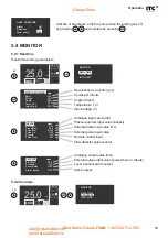
Page 35: ...PRESSURE Alarm ON Relay out ON Stop pump OFF MONITOR COUNTERS INFO UNIT REAL TIME l h 0 0 0 0 0 0 MODE 25 0 Analogue output value mA External pulse output value pulses hour or minute Level 2 sensor alarm output Alarm output Analogue input value mA Pressure sensor input value bar psi External pulse input value Hz External pulse input value Remote control input Flow detector pulse counter MONITOR RE...

Page 36: ...me hours Short circuit alarms Overload alarms High temperature alarms High temperature alarms chip Motor connection fault alarms Input voltage alarms Unit code Serial number Nominal pump flow l h or GPH Maximum pressure bar or psi Cycles min Cycle volume Reducer Calibration factor Hardware version Software version 5 4 3 Info Unit RESET COUNTERS 2 ENT YES ESC NO MONITOR REAL TIME COUNTERS INFO UNIT...

Page 37: ...tainer PUMP CHECK Make a visual auditory check of the correct operation of the pump PRIMING To facilitate pump priming open the priming valve OVERPRESSURE PROTECTION Adjust the safety overpressure or pressure relief valve to the desired pressure to protect the installation while never exceeding the nominal pressure of the pump Create Flow info createflow cz www createflow cz Distribuce Create Flow...

Page 38: ...55105 55119 55103 55 109 55 109 Pinion 55610 60304 62318 55305 Ring gear 55154 55305 55306 55601 55300 63212 63213 55304 55302 55 100 MODEL RING GEAR PINION S50 D50 55132 55129 F50 D50 55132 55129 F30 D50 55133 55106 F51 D50 55131 55129 F31 D50 55107 55106 F41 D69 55130 55128 F31 D69 55107 55106 Create Flow info createflow cz www createflow cz Distribuce Create Flow tel 420 722 712 652 ...

Page 39: ...39 Maintenance 55606 55605 59309 59353 55655 M12 73654 M2 73615 M12 C 55202 55150 29620 55149 55 100 55309 Create Flow info createflow cz www createflow cz Distribuce Create Flow tel 420 722 712 652 ...

Page 40: ...en screw M4x4 DIN 913 1 55305 Bearing 6201 2RSH 12x32x10 2 55306 Bearing 61909 2RS 45x68x12 2 55310 Bolt 4x20 E0210 A2 6 55601 Hall Sensor PCB 1 55605 Dosmart power PCB 1 55606 Power supply 240 Vac 24 Vac 1 55610 NEMA 23 step motor 1 55655 M12 3 pin male panel connector 1 55 800 1 P Double ball pipe suction valve 3 4 1 55 801 P Pipes delivery valve 3 4 1 55835 3 4 injected priming valve body 1 553...

Page 41: ...6x8 6x12 10x12 60811 1 P 62310 60813 1 P 64348 60308 55822 P 62310 60813 1 P 64348 60308 55822 P 62310 55820 P 62310 Pins Flanges 60811 1 P Flanges Pins 62310 55819 P 62310 62310 60815 1 59306 59303 59810 1 P 59303 59800 1 60813 1 P 64348 60308 60812 1 P 62310 60813 1 P 64348 60308 60812 1 P Create Flow info createflow cz www createflow cz Distribuce Create Flow tel 420 722 712 652 ...

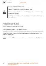
Page 42: ...ANCE Check the condition of the suction filter once a month Check the condition of the valves every 3 months or 1000 hours We recommend periodically circulating clean water through the dosing pump coinciding for example with the emptying of the tank in order to remove any precipitated remains from inside the cylinder or in the suction and discharge pipes In the event of using highly corrosive liqu...

Page 43: ...tions within the tolerated range The pump is working with overpressure Check that the line pressure is lower than the maximum allowable pressure of the unit Incorrectly dimensioned delivery pipe Shorten the delivery pipe or increase its diameter Overload AL 3 The pump is working with overpressure Check that the line pressure is lower than the maximum allowable pressure of the unit Incorrectly dime...

Page 44: ...elivery valve Clean or change valves Dirty suction filter Clean filter Air enters the suction pipe Check tightness of connection points Cavitation in suction Increase pipe diameter Reduce the suction pipe length Reduce speed by using a variator Use a less viscous liquid Pump drips liquid from bottom orifice of cylinder Damaged diaphragm Change diaphragm Create Flow info createflow cz www createflo...

Page 45: ...1 2 3 4 5 6 7 8 10 11 12 FLOW LEAKAGE PRESSURE VENTILATION RS 485 4 20 mA PULSE PULSE ALM LEVEL ALM REMOTE LEVEL 1 LEVEL 2 4 20 mA 4 20 mA ITC controllers Pulse input ITC flowmeter Remote activation Level sensors Brown Brown Brown Black White White Blue Blue 1 2 3 4 5 Black Grey 1 REMOTE 2 REMOTE 3 LEVEL 1 4 LEVEL 2 5 COMMON 24 Vdc Motor 110 240 Vac L N 59800 1 55612 Create Flow info createflow cz...

Page 46: ...Create Flow info createflow cz www createflow cz Distribuce Create Flow tel 420 722 712 652 ...

Page 47: ...as Manager WARRANTY I T C S L guarantees the product specified in this document for a period of 1 year from the date of purchase against all manufacturing or material defects provided that installation use and maintenance of the equipment are correct The equipment must be sent free of charge to our workshop or I T C S L accredited technical service and will be returned cash on delivery The equipme...

Page 48: ...nd Can Bernades Subirà P O Box 60 08130 Santa Perpètua de Mogoda BARCELONA SPAIN Tel 34 93 5443040 Fax 34 93 5443161 e mail itc itc es www itc dosing pumps com Create Flow info createflow cz www createflow cz Distribuce Create Flow tel 420 722 712 652 ...

Reviews: