7CH4Q107_E_4
DATE : 28/06/2013
REV. 4.0
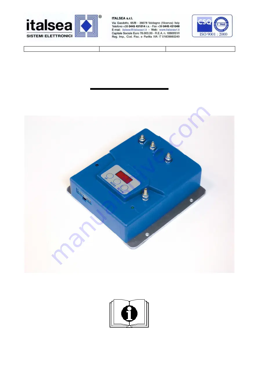
7CH4Q107
MICROPROCESSOR FOUR QUADRANT CONTROLLER FOR
PM DC MOTORS EXTERNAL PROGRAMMER
- USER’S GUIDE -
Page 1: ...7CH4Q107_E_4 DATE 28 06 2013 REV 4 0 7CH4Q107 MICROPROCESSOR FOUR QUADRANT CONTROLLER FOR PM DC MOTORS EXTERNAL PROGRAMMER USER S GUIDE...
Page 2: ...nnector Page 7 power screws Page 7 CONTROLLER SETTING 7PROGLCD HANDHELD PROGRAMMER Page 8 TESTER MODE Page 9 ALARMS Page 10 11 PARAMETERS PARAMETRS Page 12 RESET TO DEFAULT Page 13 GENERAL SETTING Pag...
Page 3: ...he current is very low so the efficiency of the system is very high The chopper is designed in accordance with the most important EC standards FEATURES POWER SUPPLY BATTERY 24 36 V RATED CURRENT 30A M...
Page 4: ...28 06 2013 7CH4Q107_E_4 3 MECHANICAL DRAWING fig 1...
Page 5: ...l abuse water and dirty Fix it with all the screws on a metal surface aluminum if possible to reduce the heath and so for longer period of work If during the standard operations the thermal protection...
Page 6: ...28 06 2013 7CH4Q107_E_4 5 COMPLETE WIRING DIAGRAM...
Page 7: ...6 DISABLE Default N C input contact When the contact is open the controller will decelerate Neutral Ramp will check if the motor voltage is near zero motor stopped and after the electro brake delay wi...
Page 8: ...WITCH N O input to V battery Pin 14 COMMON HIGH V battery output for switches Pin 15 KEY IN Key switch input V battery Pin 16 HOURMETER Hour meter output V battery when running 100mA max 4v Molex conn...
Page 9: ...voltage speed reference input internal aluminum heat sink temperature battery voltage hour meter and software release To start the programming function push the button MODE Will appear the first para...
Page 10: ...voltage measure measure unit Volts REFERENCE INPUT Vref Volts Speed reference voltage measure unit Volts potentiometer or voltage 0 5V speed reference HEATSINK TEMP T C F Internal heat sink temperatur...
Page 11: ...he speed reference to zero and open the BW switch ALARM A3 POT FAULT Potentiometer fault Check the potentiometer s wires ALARM A4 POTI OUT OF ZERO Potentiometer out of neutral position at power on Mov...
Page 12: ...ery voltage upper than 45V check the battery ALARM A10 OVERVOLTAGE Overload protection Check the motor working current and parameters rated current and overload time ALARM A11 OVERLOAD CURRENT Disable...
Page 13: ...wag potentiometer without EN switch F15 2 0 0 0 10 0 Brake delay s F16 0 0 20 Min speed of max speed F17 25 0 40 Motor s rated current In F18 60 0 60 Motor s overload time s t F19 200 50 500 Dead band...
Page 14: ...from stop position to max settled speed REVERSE RAMP Reverse direction deceleration ramp time in seconds from the current direction to reverse direction NAUTRAL RAMP Deceleration ramp time in seconds...
Page 15: ...n max speed MINIMUN SPEED Minimum speed value in percent of battery voltage BATTERY VOLTAGE Battery supply voltage set the value between options 24V or 36V RxI COMPENSATION further improve FW MAX SPEE...
Page 16: ...D REFERENCE page and confirm it by MODE button Single ended potentiometer potentiometer with two direction switches Wigwag1 potentiometer potentiometer with middle stop position and enable switches Wi...
Page 17: ...p 2 POTI COURSE no Choose tar to set poti course option and confirm it by UP button Step 3 POTI CALIBR Vzero V Set the potentiometer or throttle at STOP NEUTRAL position and confirm it by MODE button...
Page 18: ...n and confirm it by MODE button Step 4 POTI COURSE no Choose tar to set poti course option and confirm it by UP button Step 5 POTI CALIBR Vzero V Set the potentiometer or throttle at STOP NEUTRAL posi...
Page 19: ...lectro brake coil when the motor is running the coil is powered off with delay when the speed reference and direction switches are in stop position Brake ON Brake OFF Motor ON Motor OFF Time Time BRAK...
Page 20: ...on as a safety function for the operator It is realized by mean of a contact that activates the function when switched the machine will decelerate will reverse the direction at a programmed speed for...
Page 21: ...urrent as follow Imax2 In2 t K In Imax t rated motor current max motor current overload time at the max current Once calculated the K is possible to calculate the ammeter time protection at your worki...
Page 22: ...NGENEERING PROTECTED PARAMETERS IGSL DEFAULT MIN MAX 0 0 99 PGSL DEFAULT MIN MAX 0 0 99 IGCL DEFAULT MIN MAX 0 0 99 PGCL DEFAULT MIN MAX 0 0 99 LPOT DEFAULT MIN MAX 0 0 99 CPOT DEFAULT MIN MAX 0 0 99...