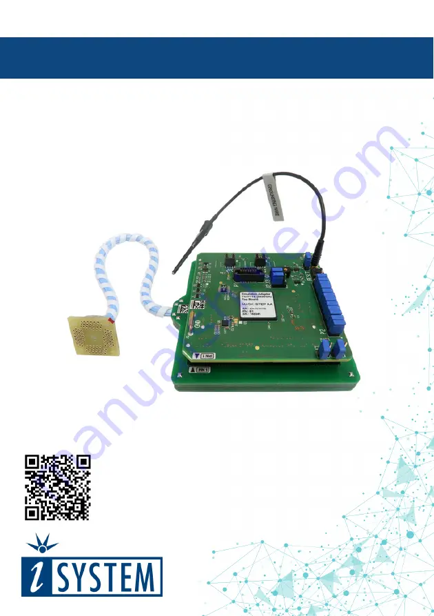
Infineon TC377TE Emulation Adapter
User Manual
V1.8
Page 1: ...Infineon TC377TE Emulation Adapter User Manual V1 8 ...
Page 2: ...ll rights are reserved Duplication of these documents is allowed for personal use In all other cases written consent from iSYSTEM is required iSYSTEM AG All rights reserved All trademarks are property of their respective owners iSYSTEM is an ISO 9001 certified company www isystem com ...
Page 3: ... 5 Adaptation packages 6 Operation 12 Jumper configuration 16 Power supply package 21 Standalone operation 22 IEA TC377TE Adaptations 23 Mechanical information 25 NQ Pack Assembly 27 HQ Pack Assembly 28 BGA Assembly 29 Recommended iSYSTEM tools 30 Schematics 31 ...
Page 4: ...ded application without influencing real time behavior It can be used to debug the most difficult and complex code defects and offers a complete trace history capture of the program execution iSYSTEM BlueBox On Chip Analyzer combined with the Infineon AGBT Active Probe or Infineon DAP DAPE Active Probe or 10 pin 1 27mm Infineon DAP2 Wide Debug Adapter or 22 pin ERF8 DAP2 Debug Adapter or 10 pin 1 ...
Page 5: ...TE The emulation device will be listed on our quotation as IEA TC377TE MC and must be ordered in addition to the other components iSYSTEM solders this device and ships the complete adapter Infineon TC377TE Emulation Adapter Package Infineon TC377TE Emulation Adapter Power supply package Power converter Power adapter Ordering code IEA TC377TE IEA TC377TE MC must be ordered along Ordering code IEA P...
Page 6: ...d Connecting part 80 pin Solder part 80 pin Socket cover optional Ordering code IEA TC377TE TC332W Ordering code IAYQPACK80SE Ordering code IANQPACK80SE Ordering code IAHQPACK80SE QFP100 Adaptation 0 4 pitch TC323 TC333 100 pin flex Conversion board Connecting part 100 pin Solder part 100 pin Socket cover optional Ordering code IEA TC377TE BTQ100W Ordering code IAYQPACK100SE Ordering code IANQPACK...
Page 7: ... IEA TC377TE TC334W Ordering code IAYQPACK144SE Ordering code IANQPACK144SE Ordering code IAHQPACK144SE QFP144 Adaptation 0 4 pitch TC364 144 pin flex Conversion board Connecting part 144 pin Solder part 144 pin Socket cover optional Ordering code IEA TC377TE TC364W4 Ordering code IAYQPACK144SE Ordering code IANQPACK144SE Ordering code IAHQPACK144SE ...
Page 8: ... Conversion board 144 pin Solder part Ordering code IEA TC377TE TC364W5 Ordering code IA144TQ SOLDER QFP144 Adaptation 0 5 pitch TC364 144 pin fixed Conversion board 144 pin Solder part Ordering code IEA TC377TE TC364F5 Ordering code IA144TQ SOLDER ...
Page 9: ...dering code IA176TQ SOLDER QFP176 Adaptation 0 5 pitch TC365 176 pin fixed Conversion board 176 pin Solder part Ordering code IEA TC377TE TC365F5 Ordering code IA176TQ SOLDER QFP176 Adaptation 0 5 pitch TC375 176 pin flex Conversion board 176 pin Solder part Ordering code IEA TC377TE TC375W5 Ordering code IA176TQ SOLDER ...
Page 10: ...QFP176 Adaptation 0 5 pitch TC375 176 pin fixed Conversion board 176 pin Solder part Ordering code IEA TC377TE TC375F5 Ordering code IA176TQ SOLDER ...
Page 11: ...steps of 3 25 mm by inserting within the Adaptation setup the optional Extender IA292LFBGA EXTENDER Not more than 2 extenders should be used since every connector affects signal integrity With no Extender the lowest point of the EA is approx 4 35 mm away from the Target With one Extender the lowest point of the EA is approx 7 6 mm away from the Target With two Extenders the lowest point of the EA ...
Page 12: ...d along Measurement Board optional IAMTC377TE Conversion board with 20 cm cable IEA TC377TE TC332W or IEA TC377TE BTQ100W or IEA TC377TE TC334W or IEA TC377TE TC364W4 or IEA TC377TE TC364W5 or IEA TC377TE TC365W5 or IEA TC377TE TC375W5 Connecting part IAYQPACK80SE IAYQPACK100SE or IAYQPACK144SE or IAYQPACK144 Solder part IANQPACK100SE or IANQPACK144SE or IANQPACK144 or User target board Emulation ...
Page 13: ...ting to the Emulation Adapter Emulation Adapter IEA TC377TE IEA TC377TE MC must be ordered along Measurement Board optional IAMTC377TE Conversion board IEA TC377TE TC364F5 IEA TC377TE TC365F5 IEA TC377TE TC375F5 Solder part IA176TQ SOLDER or IA144TQ SOLDER User target board Emulation Adapter connection scheme with fixed Conversion board ...
Page 14: ...pter Emulation Adapter IEA TC377TE IEA TC377TE MC must be ordered along Measurement Board optional IAMTC377TE Conversion board IEA TC377TE TC377 Extender optional IA292LFBGA EXTENDER For ordering the correct amount of Extenders go to the IEA TC377TE Adaptations chapter Solder part IA292LFBGA SOLDER User target board Emulation Adapter connection scheme with BGA292 Adaptation ...
Page 15: ...required when The Emulation Adapter is used as a standalone device User target doesn t provide accurate supply voltage User target doesn t provide sufficient current for the Emulation Adapter operation IEA TC377TE Emulation Adapter Top Bottom side of the Emulation Adapter ...
Page 16: ...not operate when user target board s crystal circuit is used as the clock source Typical design guideline is that the crystal should be as close as possible to the microcontroller The crystal on the user target board might not oscillate in conjunction with the Emulation Adapter when the clock lines TP21_2 TP21_3 between the crystal and the emulation device on the Emulation Adapter become too long ...
Page 17: ...ood ground connection is required connection points bridge J4 and pin J5 provide easy access to the emulation adapter GND potential J6 J7 VFLEX VAREF VFLEX If the target s VFLEX pin isn t exposed set the jumper to the position J6 to connect VEXT from the target to power VFLEX ...
Page 18: ...P pinout Signal Direction is described from the BlueBox perspective iSYSTEM BlueBox solution supporting Infineon DAP debug interface connects to the P1 connector P2 Power supply configuration Emulation Adapter Power supply is configured via the unshrouded 26 pin 2 54 mm header P2 Signal direction Signal Pin Pin Signal Signal direction User target board TVEXT 1 2 VEXT Emulation device User target b...
Page 19: ...apter simply plugs into the P2 header row providing the necessary power supply for Emulation Adapter operation LED1 indicates if power is supplied to the Emulation Adapter Refer to the microcontroller documentation for more details about power voltage designations P8 DAPE P8 connector exposes DAPE debug interface and has the following pinout Signal Direction Signal Description Signal Pin Pin Signa...
Page 20: ...I O Ground GND 11 12 nTRST DAPEN JTAG Output O Not Connected NC 13 14 CLK AGBT Clock O Not Connected NC 15 16 CLK AGBT Clock O Ground GND 17 18 TGO AGBT Trigger out I Not Connected NC 19 20 AGBT ERR AGBT Error Not Connected NC 21 22 RESET Reset I O 22 pin AGBT pinout Revision C1 Signal Direction is described from the BlueBox perspective Blue color marks the trace signals Pin 18 TGO AGBT Trigger ou...
Page 21: ... J7 NC 17 18 J8 NC 19 20 J9 GND 21 22 GND GND 23 24 GND GND 25 26 KEY U6 connector and J0 J9 jumper correlation table For example when J2 is in the 3 3V position it supplies 3 3V to the pin 6 of the U6 connector When J2 is in 5V position it supplies 5V to the pin 6 of the U6 connector pin Be careful to not supply 5V to the microcontroller power supply pin which has declared maximum voltage 3 3V Re...
Page 22: ...ly Use enclosed IEA PS Emulation Adapter Power converter and adapter Clock source If user target s crystal circuit microcontroller oscillator if available is not an adequate clock source insert appropriate crystal into the Q1 socket replace the default 10pF C7 and C8 capacitors when necessary and place jumpers J2 and J3 in 2 3 position ...
Page 23: ...00SE IANQPACK100SE IAHQPACK100S E TC324 TC334 0 4 pitch QFP144 IEA TC377TE TC334W with 20 cm cable IAYQPACK144SE IANQPACK144SE IAHQPACK144SE TC364 0 4 pitch IEA TC377TE TC364W4 with 20 cm cable IAYQPACK144SE TC364 0 5 pitch IEA TC377TE TC364W5 with 20 cm cable IAYQPACK144SE TC364 0 5 pitch IEA TC377TE TC364F5 IA144TQ SOLDER TC365 0 5 pitch QFP176 IEA TC377TE TC365F5 IA176TQ SOLDER TC365 0 5 pitch ...
Page 24: ...4 TC334 0 4 pitch QFP144 TC334 TQFP 144 TC364 0 4 pitch QFP144 TC364 TQFP 144 TC364 0 5 pitch QFP144 TC364 LQFP 144 TC365 0 5 pitch QFP176 TC365 LQFP 176 TC375 0 5 pitch QFP176 TC375 LQFP 176 The Measurement Board comes together with different pin count layout boards black panels where all the CPU signals are nicely marked Place appropriate one over the measurement board Top view of the Measuremen...
Page 25: ...anical information NQ PACK Solder part solder upper view Side view of the Solder part Solder part solder bottom view Top view of the Conversion board Top view of the Emulation Adapter NQPACK Solder pad view ...
Page 26: ... 4 IANQPACK144SE 25 18 65 18 1 0 5 0 20 17 22 0 18 35 0 4 IANQPACK176SE 29 22 65 22 1 0 5 0 20 21 20 0 18 43 0 4 You must be familiar with the SMT Surface Mount Technology soldering to solder the NQPACK to the PCB On request iSYSTEM provides this service too BGA292 Adaptation For ordering the correct amount of Extenders go to the IEA TC377TE Adaptations chapter Side view of the Emulation Adapter o...
Page 27: ...cluded with the YQPACK for fixing the YQPACK Do NOT use the screwdriver included with the NQPACK for fixing the Guides Note that you need to provide your own screwdriver 3 Connect the Emulation Adapter after checking for a match with the position of pin 1 for the YQPACK and connect the Debug Adapter Active Probe from the BlueBox to the connector on the Emulation Adapter For more information on how...
Page 28: ... Target after checking for a match with the position of pin 1 on the Target 2 Install the Microcontroller after checking for a match with the position of pin 1 on the NQPACK 4 Mount the HQPACK Socket Cover after checking for a match with the position of pin 1 on the Microcontroller HQPACK Socket Cover Microcontroller NQPACK Electronic circuit PCB ...
Page 29: ...1 for the Extender Solder part and connect the Debug Adapter Active Probe from the BlueBox to the connector on the Emulation Adapter For more information on how to connect iSYSTEM hardware refer to isystem com connect 4 Gently press with you thumb on the Target Microcontroller and with your other hand carefully align the notch on the Debug Adapter with the orientation key of the connector on the E...
Page 30: ...ctive Probes Listed Debug Adapters and Active Probes provide tracing functionality for the Infineon TC377TE Emulation Adapter Ordering code Description IC57163 Infineon DAP DAPE Active Probe IC57164 Infineon AGBT Active Probe IC50163 2 10 pin 1 27mm Infineon DAP2 Wide Debug Adapter IC50164 22 pin ERF8 DAP2 Debug Adapter Refer to the Debug Adapters User Manual for technical details on the available...
Page 31: ...on Adapter Schematics click on the link below Schematics PDF To view the Emulation Adapter Schematics Visit isystem com user manuals find your Emulation Adapter User Manual and go to the Schematics chapter or Scan the below QR code ...
Page 32: ... information provided in this document at the time of publishing Whilst iSYSTEM reserves the right to make changes to its products and or the specifications detailed herein it does not make any representations or commitments to update this document iSYSTEM All rights reserved ...