iStore - Installation Manual - June 2020
6
Electrical Connection:
Please check the electrical specification table. Under no circumstances shall the electrical lead be
converted to a 3 pin plug and connected to a General Power Outlet (GPO).
An approved AC Isolator
shall be installed within 1m of the unit.
500kPa Pressure Reduction Valve:
Pressure Reduction Valve (PRV 500)
- A pressure reduction valve of 500kPa maximum must be fitted
immediately downstream of the cold water non-return isolation valve. Failure to install a pressure
reduction valve will void the warranty. Please note cold water supply line to the tempering valve must
be run after the PRV to ensure equal supply pressure to the tempering valve. This valve is not required
shall a 500kPa PRV be installed at the water main supply to the property.
Note: In SA, WA & QLD (and some other areas of other states subject to local authority regulations) it is a
requirement that an expansion control valve be fitted between the non-return isolating valve and the water
heater.
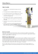
How it works
1. A fan draws in air, containing heat energy, across the
evaporator
2. The evaporator turns the liquid refrigerant into a gas
3. The compressor pressurises the refrigerant into a hot gas
4. The hot gas inside the condenser coil heats the water
inside the coil-wrapped tank
5. The refrigerant reverts back to a liquid after heating the
water and continues to the evaporator for the process to
start again
6. The cycle continues until the set target
temperature is
achieved.
7. As water is used in the home, the cycle will restart once
the temperature in the tank has dropped 11 degrees
below the target temperature.
iStore Basics


