background image


Page 7 of 43 

Low Temp Furnace Model ITL-M-17701 13-07/20 

INSTALLATION OF THE THERMOMETER SUPPORT (REMOVED FOR 
TRANSIT) 

 
This furnace is supplied with the thermometer support for the safe storage of up to four thermometers, but 
removed for transit purposes.  Please see the below image for a guide to the installation of the support to 
the furnace. 


1. 

Thermometer support  

2. 

Screw locations 


Please screw the thermometer support to the furnace in the way shown above using the screws supplied.  
Tighten sufficiently. 
 
Please take care when inserting or removing thermometers from the pocket below the support. 


Summary of Contents for ITL-M-17701

Page 1: ...England Tel 44 0 1704 543830 Fax 44 0 1704 544799 Internet www isotech co uk E mail info isotech co uk The company is always willing to give technical advice and assistance where appropriate Equally because of the programme of continual development and improvement we reserve the right to amend or alter characteristics and design without prior notice This publication is for information only ...

Page 2: ...ARTS ARE NOT COVERED BY THIS GUARANTEE INTERFERENCE WITH OR FAILURE TO PROPERLY MAINTAIN THIS INSTRUMENT MAY INVALIDATE THIS GUARANTEE Recommendation the life of your ISOTECH Instrument will be prolonged if regular maintenance and cleaning to remove general dust and debris is carried out The company is always willing to give technical advice and assistance where appropriate Equally because of the ...

Page 3: ...0 To access the NETWORK INTERFACE 20 DATA LOGGING 20 FTP SERVER ARCHIVING 21 PROGRAMMER FUNCTION 21 To create install and run a PROGRAM via the controller interface please follow the instructions below 22 PROGRAM DETAILS 22 How to create a simple PROGRAM using the controller interface 23 To enable RUN this PROGRAM 24 To edit an existing PROGRAM 24 Using the HOLDBACK feature 25 To enable this featu...

Page 4: ...C 417 Caution Hot Surface ELECTRICAL SAFETY This equipment must be correctly earthed This equipment is a Class 1 Appliance A protective earth is used to ensure the conductive parts cannot become live in the event of a failure of the insulation The protective conductor of the flexible mains cable which is coloured green yellow MUST be connected to a suitable earth The Blue conductor should be conne...

Page 5: ...is hot or cold unless wearing the appropriate protective clothing and having the necessary training 6 Do not drill modify or otherwise change the shape of the apparatus 7 Do not dismantle the apparatus 8 Do not use the apparatus outside its recommended temperature range 9 If cased do not return the apparatus to its carrying case until the unit has cooled 10 There are no user serviceable parts insi...

Page 6: ...NSTRUCTIONS 1 Slacken the central nut using the required tube spanner the insertion of a screwdriver through the tube spanner will prevent the central stud turning 2 Remove the 3 screws securing the transit clamp to the top of the unit Slacken each screw equally by degrees and then completely remove the screws 3 Gently lift the transit clamp vertically a central tube which has secured the furnace ...

Page 7: ...p to four thermometers but removed for transit purposes Please see the below image for a guide to the installation of the support to the furnace 1 Thermometer support 2 Screw locations Please screw the thermometer support to the furnace in the way shown above using the screws supplied Tighten sufficiently Please take care when inserting or removing thermometers from the pocket below the support ...

Page 8: ...IATED WITH AND THE PRECAUTIONS TO BE TAKEN WITH SUCH EQUIPMENT ELECTRICAL INSTALLATION THE FURNACES HAVE BEEN DESIGNED FOR CONVENIENT USE AND MAY BE PLUGGED TO A STANDARD THREE PIN 13 AMPERE SOCKET THEY ARE SUPPLIED SUITABLE FOR THE UK MAINS WHICH HAS LIVE NEUTRAL AND EARTH LINES THIS EQUIPMENT MUST BE EARTHED THE FURNACE IS SUPPLIED WITH A FUSE CARRIER FITTED WITH A NEUTRAL LINK THIS IS CLEARLY L...

Page 9: ...point cell is inserted is of Aluminium alloy which provides a very low thermal gradient along the core length The main furnace heater is of the parallel tube design as used at NIST A pre warming tube is provided Two entirely independent over temperature safety devices are included A dedicated on off over temperature control circuit provides active safety A fusible link in the main power circuit pr...

Page 10: ...Low Temp Furnace Model ITL M 17701 13 07 20 GENERAL LAYOUT Figure 1 Front View 1 USB Socket 2 Ethernet socket 3 Main Controller 4 Overtemperature controller 5 Main power switch Figure 2 Rear View 1 Mains power cable ...

Page 11: ...Page 11 of 43 Low Temp Furnace Model ITL M 17701 13 07 20 Figure 3 Top View 1 Gantry support 2 Pre warming pocket 3 Furnace core ...

Page 12: ...n Initially this can be quite a low value say 200 C for test purposes Now press the SCROLL and PAGE buttons together once to enter the new value and a second time to reset the controller On the second press the furnace will make a noise as the main control circuit powers up The furnace is now active and ready for use On the main controller press the SCROLL button to highlight the Setpoint box Pres...

Page 13: ...et the controller from an alarm condition you will need to press the buttons again simultaneously 5 If the controller is in the alarm condition and the complete furnace is powered down the controller will remember the condition and will still need to be manually reset when powered up again The controller installed on this equipment uses an advanced three loop controller with a multi channel sensor...

Page 14: ...ng the USER ACCESS PAGE Other features will require the user to log in as Supervisor to carry out these functions These include Adjusting the PID settings Using the Programmer function Changing the linearity settings Extracting data from the recorder function Configuration changes to the controller require you log in as Engineer to perform these functions These include Change language selection Ch...

Page 15: ...OLL button to display the SUPERVISOR screen Figure 5 9 When logged in as the SUPERVISOR the equipment will control in the normal way How to log in as the Engineer 1 Press the Page button to display the Home menu 2 Scroll to LOG IN 3 Press the SCROLL button 4 Press up to scroll to ENGINEER in dialogue box 5 Press the SCROLL button to prompt for a passcode 6 Select code 17 from the soft keyboard 7 P...

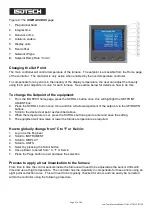
Page 16: ... controls Figure 6 The USER INTERFACE start up screen and controls 1 ISOTECH splash screen 2 PAGE button 3 SCROLL button 4 DOWN button 5 UP button Figure 7 The HOME page 1 Furnace temperature 2 Furnace setpoint 3 Furnace setpoint box 4 Data record symbol 5 PAGE button 6 SCROLL button 7 Down button 8 Up button ...

Page 17: ...ss the SCROLL button once more and this will allow adjustment of the setpoint via the UP DOWN buttons 3 Scroll to the desired set point as described above 4 When the temperature is set press the SCROLL button again to enter and save the setting 5 The equipment will now raise or lower the furnace temperature as required How to globally change from C to F or Kelvin 1 Log in as the Engineer 2 Scroll ...

Page 18: ...d enter with the SCROLL button 9 Scroll to POINT 1 and enter the value from the reference thermometer The controller is now ready to accept a value Ensure the equipment is thermally stable you will now need to use the temperature value displayed by the reference thermometer 10 Record the value on the reference thermometer and scroll to DISPLAY VALUE tab and press enter 11 This will bring up a soft...

Page 19: ...ck on the ISOTECH homepage To disable the tuning feature during a tune repeat the process above and select OFF This will now disable the tune and install the previous values How to change the Date and Time or the Language of the equipment The Date and time of the equipment can be changed to suit local time This can also incorporate the daylight saving time in the time zone of your country or regio...

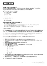
Page 20: ...ISOTECH homepage Figure 7 The data can either be extracted via the USB socket on the front panel or to a PC by means of the FTP protocol Remote Archiving using REVIEW software see page 42 for details To back up the data via USB stick on the control panel use the following procedure 1 Log in as the SUPERVISOR 2 Plug a suitable USB memory stick to the socket on the control panel Figure 1 3 Ensure th...

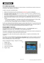
Page 21: ... instrument IP address to log in as a specific user For IE5 users Microsoft Internet Explorer displays by default history files only To quit the history folder either uncheck the Tools Internet Options Advanced Browsing Enable folder view for FTP sites option or check the Tools Internet Options Advanced Browsing Use Web based FTP option PROGRAMMER FUNCTION The equipment has an on board PROGRAMMER ...

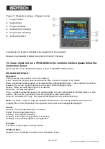
Page 22: ...ram drive This is useful if you wish to snapshot the current program and store this under a different program name Delete Allows the selected program to be deleted Delete All Deletes all programs Copy Copies the selected program for pasting either from the internal drive to the USB device or vice versa This is useful if you wish to transfer a program to other instruments Copy All As above for Copy...

Page 23: ...le Ramp style applies to all ramp segments in the program Ramp Style can be edited only when the program is in Reset mode Setpoints rates times etc are set in the individual segment configurations Rate A Ramp Rate segment is specified by a target set point and the rate at which to ascend descend to that set point Time A Ramp Time segment is specified by a target set point and a time in which to ac...

Page 24: ...ST_1 10 TEST_1 is now the default program 11 To RUN the program TEST_1 exit the PROGRAM EDIT page using the PAGE button until you see the PROGRAM homepage 12 Press SCROLL once to highlight the RESET box 13 Scroll to TEST_1 and press the SCROLL button to initiate the program The page will now change to show the current program running as figure 11 above To edit an existing PROGRAM 1 Follow the abov...

Page 25: ...ll allow the heat source to eliminate any lag between the controller and the heat source itself Holdback can be configured to hold either the segment or the complete program The USER defined value is used to define the actual value applied to it This can either be LOW where the heat source temperature is below the Setpoint The programmer will hold the value until the heat source has caught up in t...

Page 26: ... Model ITL M 17701 13 07 20 FIGURE 14 SEALED METAL FREEZING POINT CELL A High purity graphite crucible and cover B High purity graphite sleeve C High purity metal D Fused quartz envelope filled to give a pressure of 1 standard atmos ...

Page 27: ...Page 27 of 43 Low Temp Furnace Model ITL M 17701 13 07 20 FIGURE 15 SEALED METAL FREEZING POINT CELL BODY DIMENSIONS ...

Page 28: ... C Furnace cavity internal diameter 54mm 2 12 cylindrical depth 368mm 14 5 D Furnace block E Parallel wire heater including thermal fuse F PRT for temperature control G Over temperature detection thermocouple H Fiberfrax insulation chopped bulk fibre I Ceramic support post J Temperature controller K Over temperature controller L On Off power switch ...

Page 29: ...he monitor is removed to a rack and replaced by a rod of quartz at ambient temperature This initiates nucleation After 2 minutes the rod can be removed and replaced by the monitor again This procedure creates a radial freeze from the inside and outside walls of the cell towards the centre If the cell is left too long in the furnace without initiating the freeze as described above nucleation will o...

Page 30: ...ient air Continue monitoring until the temperature begins to rise Return the cell to the furnace remove the monitor thermometer and replace with a quartz rod from ambient temperature After 2 minutes remove the rod and replace the thermometer When the monitoring thermometer has shown no change for some minutes the plateau has been achieved A typical melt freeze sequence is shown in Figure 17 A usef...

Page 31: ...Initial temperature rise B Temperature arrest during melt C Furnace controlled temperature D Temperature drop caused by furnace controller adjustment E Depth of supercool particularly pronounced for tin F Plateau showing constant temperature during freeze G Temperature drop after completion of freeze ...

Page 32: ...t 2 hours This operation outgasses the basket and insulation which may smoke and discolour during this first temperature excursion The cell can then be inserted into the basket in readiness for use If removing the cell with a thermometer in its pocket e g tin cell extreme caution is necessary in applying support by means of the diametrically pivoted handle The handle will need to be maintained in ...

Page 33: ...Page 33 of 43 Low Temp Furnace Model ITL M 17701 13 07 20 ...

Page 34: ...Low Temp Furnace Model ITL M 17701 13 07 20 FIGURE 18 LOW TEMPERATURE FURNACE CELL ASSEMBLY A Fibreboard B Aluminium Foil C Fibreboard D Fibreblanket E Fibrewool F Fibreblanket G Furnace Block H Basket I Kaowool Disc ...

Page 35: ... material in a sealed enclosure from which all other materials including air have been evacuated leaving a space to be filled by the vapour phase at a pressure appropriate to the temperature When the three phase solid liquid vapour condition has been established these parameters will settle to their unique triple point values The defining fixed points above 0 C are liquid solid equilibria of high ...

Page 36: ...ficulties of setting up conditions to facilitate this measurement can conveniently be circumvented by carrying out the alternative procedure of comparison calibration in which the thermometer is compared in an environment of boiling nitrogen to a similar thermometer which possesses a calibration traceable to national standards A separate manual describes the nitrogen boiling point apparatus The te...

Page 37: ...3 ITL M 17668 ITL M 17701 3 4 TIN FP 231 928 505 078 3 3 2 2 ITL M 17669 ITL M 17701 3 4 ZINC FP 419 527 692 677 4 3 2 7 ITL M 17671 ITL M 17701 2 3 ALUMINIUM FP 660 323 933 473 7 0 1 6 ITL M 17672 ITL M 17702 SILVER FP 961 78 1234 93 6 0 5 4 ITL M 17673 ITL M 17702 NOTES 1 TP Triple Point MP Melting Point FP Freezing Point 2 Pressure corrections that apply to triple point and to other sealed cell...

Page 38: ...e it must still be regarded as a kilogram or more of mass loosely contained in a frangible shell Cells should never be inverted although they may be slowly turned to the horizontal and laid on their sides Transporting cells by common carrier is not recommended and as furnished they must be hand carried A broken cell cannot in general be repaired although a cell which is broken but sufficiently int...

Page 39: ...e pressure at the freeze point may as a consequence be incorrect and more seriously contamination may occur Sealed quartz cells can be used for thousands of hours without devitrification if precautions are taken to ensure that the outside surface is scrupulously clean before raising them to temperature Any surface dirt a water spot or a single fingerprint is a potential seed for devitrification Be...

Page 40: ...ever the technique requiring association of cells with other equipment involves subtlety and operator sensitivity Before relying upon measurements made in them the operator should perform enough freezes to become familiar with the cell furnace control monitoring thermometer and readout as a system to ensure that the melt is clearly identifiable and sufficiently consistent ...

Page 41: ... Temp Furnace Model ITL M 17701 13 07 20 ADDITIONAL SERVICES AND INFORMATION Isotech operates one of the world s most comprehensive UKAS supervised Laboratories Training is available to customers at an agreed daily rate ...

Page 42: ...purchased it allows for fully automatic calibration including certificate printing and the calculation of coefficients Refer to the Isotech I Cal EASY handbook and help system for more details Figure 19 PROGRAM EDITOR This allows set point programs to be created on a PC and uploaded to the furnace Figure 20 Installation instructions are included with the download ...

Page 43: ...m this database to the chart or spreadsheet The chart spreadsheet can be configured to include one or more channels from one or all connected instruments It is also possible to archive instrument history files to a memory stick and to use this to transfer the data to the pc The user name and password are both history and they are not editable These applications can be downloaded from the Isotech w...

Reviews: