background image

isel

-PSPCI V3 User Manual 

3.6.2  Adjusting the axis- and reference directions of gantry units 

 
Follow the instructions for the initiation of the individual axes. 


3

3

.

.

6

6

.

.

2

2

.

.

1

1


X-Axis

X-Axis


1)  Click on the button 

„I/O – Actions“

 in MtConfig. Deactivate the hardware limit switch of 

the X axis by removing the check in the first check box of the left. (also see chapter: 
3.5.2.5 I/O- Actions) 

 
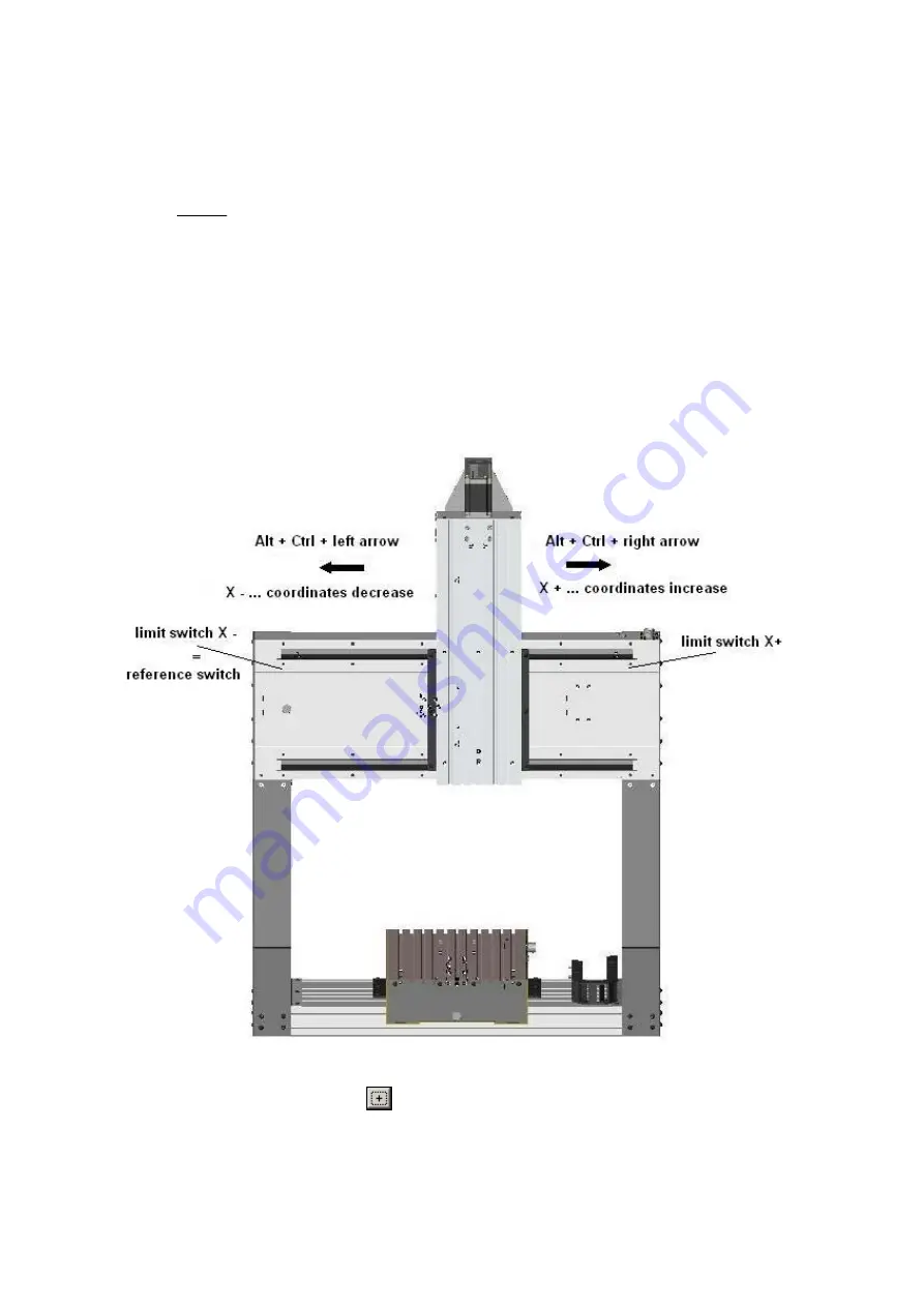
2)  Now move to the field „Axes“ within the driver parameters. Check the alignment by 

manually moving the X axis. Therefore use the short cut 

Alt + Ctrl + left arrow

 and 

Alt 

+ Ctrl + right arrow  
 

The following picture shows the correct axis alignment. 


In case the X axis does not move as shown in the picture, please change the direction of 

the axis by pushing the button 

 for the direction of the axis. 

 
Click the button “Save“ in the main window of MtConfig to save the new adjustments. 
Check the alignment again. 

Seite - 23 

Summary of Contents for PSPCI

Page 1: ...isel automation GmbH Co KG D 36466 Dermbach Untere Röde 2 isel PSPCI User manual for stepper motor control PSPCI Version 3 036964 84510 036964 844 ...

Page 2: ...scriptions of each individual company are generally subject to protection of trademarks and patent law All rights reserved It is not permitted to reproduce or electronically process duplicate or spread any part of our prints in any way print copy etc without written permission of isel automation Producer iselautomation GmbH Co KG Bürgermeister Ebert Straße 40 D 36124 Eichenzell Tel 06659 981 0 Fax...

Page 3: ... Starting the adjusting program 4 3 3 The windows of MtConfig 5 3 3 1 The Main Window 5 3 3 2 The Toolbar 5 3 3 3 Select Parameters 6 3 3 4 Save and Close 6 3 3 5 The Coordinate Window 6 3 3 6 Inputs Outputs 7 3 3 7 The Editor 7 3 3 8 Error Status 7 3 4 Notes 8 3 4 1 Referencing 8 3 4 2 Manual Jogging 8 3 5 Adjusting Parameters 9 3 5 1 Driver Parameters 9 3 5 1 1 Addresses 9 3 5 1 2 Timer 9 3 5 1 ...

Page 4: ... point 22 3 6 2 Adjusting the axis and reference directions of gantry units 23 3 6 2 1 X Axis 23 3 6 2 2 Y Axis 25 3 6 2 3 Z Axis 27 3 6 3 Adjusting the axis and reference direction of flatbed units 29 3 6 3 1 X Axis 29 3 6 3 2 Y Axis 29 3 6 3 3 Z Axis 30 3 7 Optimising 31 3 7 1 Procedure 31 3 7 2 Further details for the optimisation 32 3 7 3 The monitor window 33 ...

Page 5: ...tion units become dispensable The result is a favourable cost performance ratio among an easy assembly and initiation For many years we have been offering systems basing on stepper motor controls which have been applied in many areas of production automation research and training The control PSPCI has been developed to continue this product line It is a stepper motor control which was implemented ...

Page 6: ... the fixing screws for the PCI slot plates 3 Now look for an unoccupied PCI bus slot 4 Remove the according slot plate of the PCI slot 5 Now plug the PSPCI stepper motor control into the slot Make sure the card was plugged in correctly 6 Fix the card with screws 7 Close the casing of your PC 3 Installation of drivers The PCI card PSPCI will automatically be identified when booting Windows for the ...

Page 7: ...2 Pulse Z 21 Pulse A 3 Pulse B 22 Direction X 4 Direction Y 23 Direction Z 5 Direction A 24 Direction B 6 24VDC 25 12VDC 7 User output 1 26 User output 2 8 User output 3 27 Output Spindle Start 9 Output Enable output stages 28 10 GND 24V 29 positive limit switch A 11 Reference switch negative limit switch A 30 positive limit switch Z 12 Reference switch negative limit switch Z 31 positive limit sw...

Page 8: ...e and check the parameters of a running machine While working with MtConfig you can display the current coordinates reference the axes display Inputs and Outputs issue motion commands from the editor and display values perform manual jogging with your keyboard Notice when using MtConfig Start MtConfig only out of a folder which contains the configuration files and MTasc dll MtConfig uses MTasc Nev...

Page 9: ... for saving your settings and closing the program On the right side you will find helpful information related to the parameter or button selected 3 3 2 The Toolbar The toolbar shows the following buttons from left to right referencing of the axis enable disable watching of the range limits Stop motion F9 display coordinates display inputs and outputs open the editor The text field to the right con...

Page 10: ...u will be prompted for saving the changes if there are any 3 3 5 The Coordinate Window The coordinate window shows the current coordinates of the machine Mtasc is able to manage several coordinate systems object coordinates which are based on a fixed system of machine coordinates If you press Shift F1 to Shift F7 you can change between the following displays Shift F1 Display Off Shift F2 Object Co...

Page 11: ...you press Strg Enter the following part of the input will be executed the highlighted text if there is any the line where the keyboard cursor is located if there is no highlighted text The example on the right shows the input AxisLetters which is not highlighted Strg Enter will therefore execute the whole line and show the result XYZ on the bottom of the Editor 3 3 8 Error Status If an errors occu...

Page 12: ...dow along with name and path of the file and the line in which the error occurred 3 4 Notes 3 4 1 Referencing When referencing the axes in order Z X Y A B will be moved towards one end to find the appropriate zero position Before referencing the following values have to be assigned The output addresses for the axes The moving direction of the axes axes The direction used to reference reference run...

Page 13: ... frequency indicates how often the real time loop is called per second At the same rate the position of the machine is calculated The background frequency is used for example to configure the cycle speed of the stepper motors The frequency must be much higher than the control cycle frequency If a driver is in use which does not need a background frequency enter 0 Delay inserts extreme short delays...

Page 14: ...affect on all further axis Other inputs for residual axis will be ignored The values in the figure can be used for machines with ball screw spindles pitch 4 5 10 mm For belt drive slides e g perimeter of belt pulley is 70mm and gear 2 1 speed values of 800 mm sec and accelerations of 2000 3000 mm sec2 can be put in here The pre adjusted value for Actuate Trailing Error is 12100 The value for Speed...

Page 15: ...hich direction the axis is to move with increasing increments These leading signs should be adjusted thusly that each axis moves in manual jogging in the direction you expect due to the keyboard input The type of the axis L R linear or rotary axis Calibration Indicate the distance one axis moves per increment You can put in this value directly or click on Formula You will then see an input window ...

Page 16: ...ction ratio is indicated through revolutions output end roe revolutions motor end rme Confirm the adjustments with OK Rotary Tilting axes You have to indicate the following parameters pitch For tilting axes the adjustment value has to be 360 steps per revolution This value indicates the number of steps per revolution of the stepper motor The most common stepper motors make 200 full steps per revol...

Page 17: ...he check boxes on the right If the range limit watching is activated and the machine crosses the border it will stop moving immediately and report the error in the error status window The machine has to be moved in a permitted area to continue 3 3 5 5 1 1 7 7 Manual Moving Manual Moving On this pane you can set up all needed values for manual moving minimum distance describes the distance the axis...

Page 18: ...n this pane you indicate the number of axes For each axis you have to indicate The axis label The direction of referencing The distance between the referencing point and the zero point of the axis Whether referencing takes place or not The number of the input for the reference switch The referencing speed fast is the speed to approach the reference switch With slow the axis is moved off the switch...

Page 19: ...bits The inputs will only be read if is selected Each change of the output state will be written immediately to the corresponding address The gained values can be re imported through appropriate outputs by selecting The LED shows the status of the bits read Deselected grey Input bit 1 red Input bit 0 blue Non inverted bits are shown normally Inverted bits are shown in an inverted mode Deselected b...

Page 20: ...module It should not be changed under any circumstances because it is being scanned periodically by the control to evaluate a case of Emergency Stop If there is no safety circuit module used this input has to be connected with 24VDC The indicated mode MMAP of inputs no 1 12 is the so called Memory MAP mode This means that the inputs are not read directly through the hardware but through the two MA...

Page 21: ...Switch Y 5 MMAP virtuell 0x10 4 Limit Switch Z 6 MMAP virtuell 0x20 5 Limit Switch Z 7 MMAP virtuell 0x40 6 Limit Switch A 0 8 MMAP virtuell 0x80 7 Limit Switch A 9 MMAP virtuell 0x01 8 Input Stop switch 10 MMAP virtuell 0x02 9 Input Start switch 11 MMAP virtuell 0x04 10 User Input 1 12 MMAP virtuell 0x08 14 Input Power_ok 13 PTI2 0x00B0 0xFF 0 7 Map Port 0 14 PTI2 0x00C0 0xFF 8 12 Map Port 1 Chan...

Page 22: ...dard configuration of the outputs with information about port numbers addresses and bit numbers Nr Typ Adresse Bit Maske Inv Bit Maske Funktion 1 PTI2 00A0h 0x01 0x00 Output Enable amplifiers 2 PTI2 00A0h 0x02 0x00 Output Brake 3 PTI2 00D0h 0xFF 0x00 Analogue output 0 10V Port 4 PTI1 0020h _ MotOn Off virtual output Changes should only be made regarding the description of the user ouputs Changes o...

Page 23: ...displayed inverted Faded out bits are displayed as un logged The following chart shows the pre adjusted configuration of the expanded inputs Port No 1 with address 00C0h Map Port 1 Map1 with device type PTI2 Bit Addr Application Logical Port Plug 1 0x01h Input Stop button I1 1 X21 2 0x02h Input Start button I2 2 X27 3 0x04h User Input I2 3 X28 6 0x20h Input Power_ok X29 Mask of both ports Port No ...

Page 24: ...inputs defined on these MAP ports reflect the current condition of the physical inputs of the PSPCI card The six check boxes serve the configuration of the cache writing and reading direction Only the first check box on the left is of interest By checking the box the MAP port is activated The entries from no 3 to no 10 define the actual assignment of the physical inputs to the MAP Ports For each l...

Page 25: ...inguished Gantry units e g EuroMod P Series The machine table Y axis carries the clamping plate for the work piece It moves in positive Y direction from the tool tip when moving towards the operator Flatbed units e g EuroMod F Series FlatCom Series OverHead Series The clamping area for the work piece is solidly fixed on the machine frame A Y movement of the tool in positive direction Y goes away f...

Page 26: ...e axis is explained in the subchapters of each machine type 3 6 1 Starting point Please check all adjustments of drivers and Mtasc parameters of the previous chapters Check if the ports on the circuit board are correctly Are the motor cables plugged in correctly Are the signal cables for limit switches and brake plugged in correctly Are the signal cables of the SK module plugged in correctly Are t...

Page 27: ...ft also see chapter 3 5 2 5 I O Actions 2 Now move to the field Axes within the driver parameters Check the alignment by manually moving the X axis Therefore use the short cut Alt Ctrl left arrow and Alt Ctrl right arrow The following picture shows the correct axis alignment In case the X axis does not move as shown in the picture please change the direction of the axis by pushing the button for t...

Page 28: ... switch Now the LED has to be blue again Repeat this step again for the other limit switch Move the axis by pushing Alt Ctrl right arrow Also check the functioning of the limit switch 4 After you have checked both hardware limit switches you have to adjust the referencing direction For this purpose you have to move the axis to the middle of the traverse range Click on Test all the way on the right...

Page 29: ...Axes within the driver parameters Check the alignment by manually moving the Y axis For this use the short cut Alt Ctrl up arrow and Alt Ctrl down arrow The following picture shows the correct axis alignment In case the Y axis does not move as shown in the picture please change the direction of the axis by pushing the button for the direction of the axis Click the button Save in the main window of...

Page 30: ...itch Now the LED has to be blue again Repeat this step again for the other limit switch Move the axis by pushing Alt Ctrl down arrow Also check the functioning of the limit switch After you have checked both hardware limit switches you have to adjust the referencing direction For this purpose you have to move the axis to the middle of the traverse range Click on Test all the way on the right withi...

Page 31: ... Axes within the driver parameters Check the alignment by manually moving the Z axis For this use the short cut Alt Ctrl page up and Alt Ctrl page down The following picture shows the correct axis alignment In case the Z axis does not move as shown in the picture please change the direction of the axis by pushing the button for the direction of the axis Click the button Save in the main window of ...

Page 32: ...from the limit switch Now the LED has to be blue again Repeat this step again for the other limit switch Move the axis by pushing Alt Ctrl page down Also check the functioning of the limit switch 4 After you have checked both hardware limit switches you have to adjust the referencing direction For this purpose you have to move the axis to the middle of the traverse range Click on Test all the way ...

Page 33: ...it switch of the Y axis by removing the check in the first check box of the left also see chapter 3 5 2 5 I O Actions 2 Now move to the field Axes within the driver parameters Check the alignment by manually moving the Y axis For this use the short cut Alt Ctrl up arrow and Alt Ctrl down arrow The following picture shows the correct axis alignment In case the Y axis does not move as shown in the p...

Page 34: ... limit switch Move the axis by pushing Alt Ctrl down arrow Also check the functioning of the limit switch After you have checked both hardware limit switches you have to adjust the referencing direction For this purpose you have to move the axis to the middle of the traverse range Click on Test all the way on the right within the entry field of the according axis Watch the movement of the axis If ...

Page 35: ...osition which is to be the 0 position if necessary do so by manual jogging 4 If necessary reset the current position of the machine with 0 3 5 Adjust the speed with the slide control 4 The speed can also be changed while moving 6 If necessary adjust the acceleration 5 7 Start the movement by clicking on MOVE 6 8 You can change the parameters during the moving process To do so click into the field ...

Page 36: ... 3 7 2 Further details for the optimisation If the parameters have to be completely recalibrated it is useful to reset the D and I values if available and increase the P values until the machine runs with a fixed noise without becoming loud After that the D controller will be raised until the target actual deviation displayed in the monitoring window are minimal This process can be automatically s...

Page 37: ...e above the horizontal line the current machine velocity is lower than the target velocity Adaptations 1 Select the axes with the Axis selection 1 2 Change the maximum value of the scale with the scale factor 2 3 Select between bar and point display with the display selection 3 4 If you stop the display 4 another button Details appears not visible here and a block of the upper line is marked by a ...

Reviews: