IGEP
TM
SMARC iMX6
Hardware Reference Manual
ISEE 2007 S.L. All rights reserved, IGEP is a registered trademark from ISEE 2007 S.L. The following is provided for informational purposes only.
NIF:ESB64377005 Document:
MAN-IGEP0046-001
/ Revision:
1.3
/ Date:
23/06/2016
27
4.11
CAN BUS: CONTROLLER AREA NETWORK
The module can be integrated in a global system using the serial standard CAN Bus. The CAN Bus is a
standard designed to allow microcontrollers and devices to communicate with each other without a host
computer. It’s a differential half duplex data bus, using shielded or unshielded twisted differential pair wiring,
with an impedance termination of 120Ω at the endpoints of the bus. Nodes on the bus are arranged in daisy-
chain fashion.
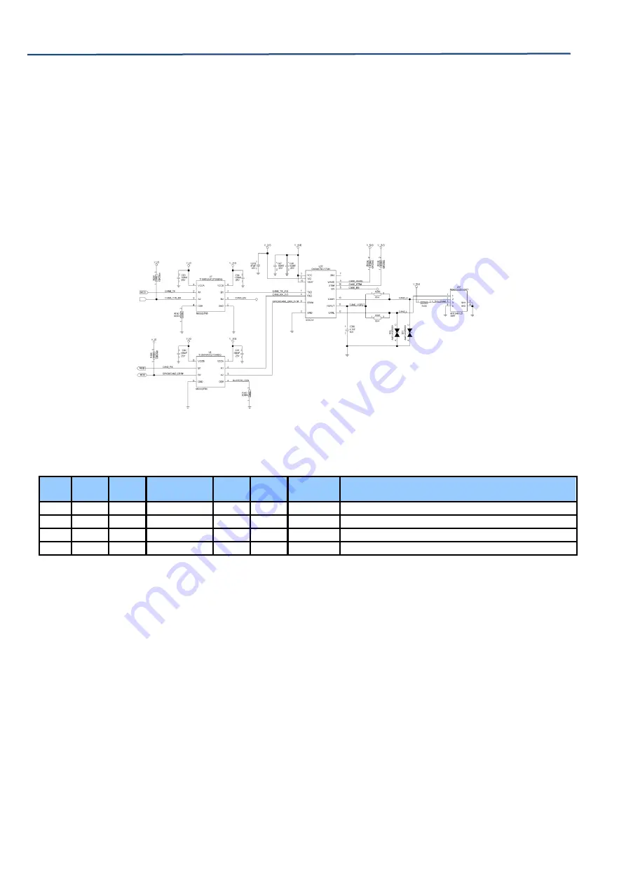
A CAN Transceiver is needed on the baseboard to connect the system to the CAN Bus. In the next example
(page 61 of SMARC Design Guide V_IO=1V8), are showing this application using the NCV7341 chip (it’s a high-
speed CAN Transceiver).
Figure 20 CAN Bus circuit example
Pin
Volt
Level
Dev
Pin
Main Function
Main
MUX
Type
Fixed
Function
Comments
P143
1V8
R3
CAN0_TX
3
OUT
NO
CAN1 Transmission Line
P144
1V8
W4
CAN0_RX
2
IN
NO
CAN1 Reception Line
P145
1V8
T6
CAN1_TX
0
OUT
NO
CAN2 Transmission Line
P146
1V8
V5
CAN1_RX
0
IN
NO
CAN2 Reception Line
Table 15 CAN pins


