IRT Electronics DDA-4007 User Manual Download Page 5

4007-dda.ib.rev1.doc 

Page 5 of 12 

15/09/2008 

Installation 

Pre-installation: 


Handling: 

 
This equipment may contain or be connected to static sensitive devices and proper static free handling precautions 
should be observed. 
 
Where individual circuit cards are stored, they should be placed in antistatic bags. Proper antistatic procedures 
should be followed when inserting or removing cards from these bags. 
 

Power: 

 
AC mains supply:   Ensure that operating voltage of unit and local supply voltage match and that correct rating 

fuse is installed for local supply. 

 
DC supply:  

Ensure that the correct polarity is observed and that DC supply voltage is maintained within 
the operating range specified. 


Earthing: 

 
The earth path is dependent on the type of frame selected. In every case particular care should be taken to ensure 
that the frame is connected to earth for safety reasons. See frame manual for details. 
 

Signal earth: 

For safety reasons a connection is made between signal earth and chassis earth. No attempt should be 

made to break this connection. 
 

Installation in frame or chassis:


See details in separate manual for selected frame type. 
 

Link Settings:


LK1 is factory set for a contact make to ground on signal failure at SK10 pin 2 on the rear panel, move LK1 from 
the normally closed (N/C) to the normally open (N/O) position for a break to ground on signal or power loss. 
 
Link LK2 closed reduces the input equalisation to 200m for use in noisy environments or when a short input cable 
is used. 


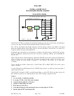
Digital Video Connections:


Input and outputs are 75 

 BNC type for connection with high quality 75 

 coaxial cable. Input is self-terminating.


Front Panel Indicators:


The presence of 270 Mb/s locked signal is indicated by the ‘SIGNAL PRESENT’ front panel LED (green). 
 
The presence of the in5 Vdc supply is indicated by the front panel LED (green). 
 

Summary of Contents for DDA-4007

Page 1: ...d and manufactured in Australia IRT can be found on the Internet at http www irtelectronics com I R T Electronics Pty Ltd A B N 35 000 832 575 26 Hotham Parade ARTARMON N S W 2064 AUSTRALIA National P...

Page 2: ...turn 11 Drawing Index 12 This instruction manual applies to DDA 4007 later than S N 0809051 Operational Safety WARNING Operation of electronic equipment involves the use of voltages and currents that...

Page 3: ...s to provide the number of outputs required This provides a more economic solution than using multiple reclocking DA s and minimises jitter increase due to unnecessary re clocking The rear assembly no...

Page 4: ...ators Power LED green for 5 V Signal present LED green when signal present Alarm Signal loss Contact closure Link selectable NO NC Power requirement Voltage 28 Vac CT 14 0 14 or 16 Vdc Consumption 2 5...

Page 5: ...hat the frame is connected to earth for safety reasons See frame manual for details Signal earth For safety reasons a connection is made between signal earth and chassis earth No attempt should be mad...

Page 6: ...up with the three sets of multipin sockets on the main PCB module Align all pins and then gently press the SMU 4000 all the way down into place If the SMU 4000 is not already programmed with the corr...

Page 7: ...l connector diagrams The following front panel and rear assembly drawings are not to scale and are intended to show relative positions of connectors indicators and controls only SK10 2 Alarm SK10 1 Gn...

Page 8: ...that information into a form compatible with SNMP The agent therefore acts as an interface between the NMS and the managed devices The NMS sends a request message and control commands for the managed...

Page 9: ...ed a plug in SMU 4000 module with a program relevant to the module that it is plugged into Depending on the module besides the module identification parameters such as alarm states inputs and controls...

Page 10: ...tional plug in SMU 4000 SNMP module programmed with firmware to suit and installed in an IRT 4000 series frame with SNMP capability it is possible to remotely monitor the presence of an input and the...

Page 11: ...extended by IRT only to the extent obtainable from the component supplier Equipment return Before arranging service ensure that the fault is in the unit to be serviced and not in associated equipment...

Page 12: ...the diagrams are optional and are not included on standard production units They are shown to assist with interpretation of additional or optional functions which may be included or are necessary for...

Page 13: ...100nF 5V 5V MON O P SK101 SIGNAL grn 2 1 R39 560R 2 1 LD2 HLMP 1503 5V ALARM CIRCUIT CONTACT CLOSURE OR BREAK TO GROUND ON ALARM AS SET BY LK1 3 2 1 Q1 BSS123 1 2 C37 4u7 R1 R9 220R L1 L9 15nH 3 8 RL...

Reviews: