


4007-dda.ib.rev1.doc
Page 4 of 12
15/09/2008
Technical Specifications
DDA-4007
Video input:
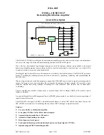
Number 1.
Impedance 75
Ω
.
Return loss
>15 dB 5 MHz to 270 MHz.
Equalisation
Automatic, better than 250 metres at 270 Mb/s for Belden 8281 or equivalent cable
(reduces to approx. 200m when LK2 is closed).
Video outputs:
Number
8 ASI or SDI plus one front panel monitoring output.
Type Reclocked.
Level 800
mV
±
10% into 75
Ω
.
Impedance 75
Ω
.
Return loss
>15 dB 5 MHz to 270 MHz.
DC offset
Nil.
Performance:
Reclocking
Factory set for 270 Mb/s operation.
Rise time
<1.0 ns, (700 ps typically).
Residual jitter
<0.1 UI (measured with up to 300m of Belden 8281 or equivalent cable).
Connectors:
BNC 75 Ohms.
Indicators:
Power
LED (green) for +5 V.
Signal present
LED (green) when signal present.
Alarm:
Signal loss
Contact closure. Link selectable NO/NC.
Power requirement:
Voltage
28 Vac CT (14-0-14) or
±
16 Vdc
Consumption 2.5
VA
Other:
Temperature range
0 - 50° C ambient.
Mechanical
Suitable for mounting in IRT 19" rack chassis with input, output and power
connections on the rear panel.
Finish:
Front panel
Grey background, black lettering & red IRT logo.
Rear assembly
Detachable silk-screened PCB with direct mount connectors to Eurocard and
external signals.
Dimensions
6 HP x 3 U x 220 mm IRT Eurocard.
Standard accessories
Rear connector assembly with matching connector for alarm output.
Optional accessories
SMU-4000 SNMP plug-in module for use with 4000 series frame fitted with SNMP
“Agent”.
Due to our policy of continuing development, these specifications are subject to change without notice.