background image


12


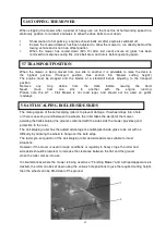
When  stopping  the mower  after a  period  of  heavy  use  run  the machine  at half  working  speed in a 
stationary position, for at least 4 minutes, to allow the drive belts to cool down.  

1


Show caution to hot parts e.g. engine exhaust, belts etc after engine is switched off.  

2


Ensure the mower drawbar has been adjusted to allow the mower to run directly behind the 


towing vehicle and is not in an offset position  

3


When  the  mower  has  cooled  down  (Min  1hr  after  last  used)  ensure  all  grass  has  been 


removed from engine cooling fins, drive belt area, and rotors before operating again.  


When  the  mower  is  being  moved  from  one  site  to  another  it  is  advisable  to  raise  the  deck  to  
the  highest  position  (Transport  position,  See  section  5.3  “Mower  cutting  height”)  
The  engine  must  be  stopped  and  the  blades  at  a  standstill  before  adjusting  to  the  transport  
position.  
Remove 

any 

crop 

debris 

from 

the 

deck 

before 

leaving 

the 

field.  

Never 

move 

from 

one 

site 

to 

another 

with 

the 

engine 

running.  

Please  note  the  AT  –  Flail  Mower  is  not  road  legal,  and  should  not  be  used  on  public  
roadways  


The main purpose of the anti scalping roller is to prevent damage. If a wheel drops into a hole, 
or there is uneven ground between the wheels, the roller takes the weight of the mower, 
avoiding the flails scalping the ground; combined with the side skids the mower provides good  
protection to the rotor. 
The anti scalping roller has the added advantage of-enabling kerb side grass to be cut with no 
difficulty, by allowing the wheel to hang over the kerb edge.  
The factor pre-set position of the anti scalping roller and side skids are suitable for most 
situations.  
However, if the mover is used in rough conditions or regularly in heavy crops, the roller and 
side skids should be lowered, to increase the clearance between the flail and the ground  
when the roller comes into use.  

In circumstances where the mower is being used as a “Finishing Mower” and a striped appearance is 
desired, the roller can be set down using the various hole positions to give the required cutting height, 
then the wheels can be lifted clear of the ground.  


5.6 STOPPING THE MOWER 


5.7 TRANSPORT POSITION 


5.8 ANTI-SCALPING ROLLER/SIDE SKIDS


Summary of Contents for ATV Series

Page 1: ...ANUAL ATV SEERIA HOOLDUSNIIDUK KASUTUSJUHEND READ AND FOLLOW ALL SAFETY AND OPERATING INSTRUCTIONS LOE JA JÄLGI KÕIKI OHUTUS JA KASUTUSJUHISEID KEEP THIS MANUAL FOR FUTURE REFERENCE HOIDKE KÄESOLEV JUHEND EDASPIDISEKS KASUTAMISEKS ALLES ...

Page 2: ... the terms of the guarantee Märkige niiduki seerianumber ja ostukuupäev allpool toodud väljadele Müüja vajab seda teavet et teenindada teid varuosade tellimise korral kiiresti ja tõhusalt Kui osi on tarvis vahetada kasutage ainult originaalvaruosi Garantiiremondi vajaduse korral esitage see registreerimise blankett koos algse müügiarvega garantiiteenuse tellimiseks müüjale IRON BALTIC OÜ Põldmäe t...

Page 3: ...tting Height 10 5 4 Starting The Engine 10 5 5 Forward Speed 11 5 6 Stopping The Mower 12 5 7 Transport Position 12 5 8 Anti scalping roller Side skid s 12 6 Maintenance Schedule 13 6 1 Engine 13 6 2 Excess Crop Build Up 13 6 3 Visual Check 14 6 4 Tyre Pressures 14 6 5 Rotor Bearing Inspection 14 6 6 Wheel Bearing Inspection 14 6 7 Oil Coupling Bush Wear 15 6 8 General Inspection 15 6 9 Rotor Flai...

Page 4: ... it has been designed to cope with a wide range of conditions Flail mower incorporates easy height adjustment range of engine options and a full width anti scalping roller to avoid damage to machine The mower is constructed from 4mm steel for added strength all fittings are of high quality to ensure years of trouble free use Engines used may vary but all are accompanied by the engine manufacturers...

Page 5: ...Note For work on slopes or uneven ground the ratio will need to be reduced Braking Fit 1 Brakes to trailed equipment This helps prevent jack knifing when braking or traveling downhill 2 Over run brakes which come into action whenever the ATV brakes are applied 3 A manually operated parking brake operable from the driving position This provides control for use when going up slopes Hitching and load...

Page 6: ... select and use safe routes Using an ATV read the manufacturer s instruction book and take note of the safety advice given Choose an ATV with enough power for the work you want it to do Four wheel driver will give better traction and mobility and may provide a margin of safety Choose a safe route Be aware that increased speed greatly increases the risk of instability and risk of and overturn Train...

Page 7: ...running Ensure engine is stopped and the rotor has finished rotating before any servicing takes place to your mover 14 DO NOT Operate the mower in Dark conditions unless suitable artificial light is used 15 DO NOT Operate if excessive vibration occurs stop the machine immediately and view maintenance chart 16 DO NOT Climb on the mower 1 DO Follow Engine manufactures guideline 2 DO Ensure all spect...

Page 8: ...ators before using review safety procedures regularly Ensure that all guards are in place before operating Keep Hand Feet Hair and Clothing away from all moving parts Avoid waring loose clothing whenever possible Maintain as per schedule in the safety procedures Especially Blades and Securing Hardwar due to hazard they present should any part break loose during operation During maintenance use sui...

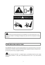
Page 9: ...ury or equipment damage When used with and ATV or compact tractor ear defenders should be worn Under normal working conditions a noise level of 83 decibels would be usual in the case protection is advised The above decals should be located on your Flail Mower If any of the above decals are not located on your Mower or are damaged in damaged in any way contact for some replacement decals before use...

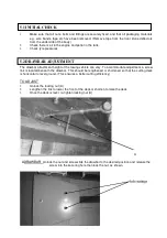
Page 10: ...o accommodate adjustment a screw link is located beneath the drawbar This should be lengthened or shortened so that the cutting deck is horizontal to level ground This ensures a better cutting efficiency TO ADJUST 1 Unlock the locking nut A 2 Lengthen the link to lower the front of the deck or shorten to raise the deck 3 Once the deck is level re tighten locking nut A A ADRAWBAR Unlock the nut and...

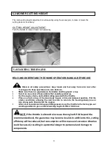
Page 11: ... with the throttle 4 Place one foot on top of the deck body to give a firm and balanced position Pull the starter cord firmly allowing the cord to return to return to the housing slowly one or two strong pulls should start the engine 5 After a few seconds warming up at idling speed move the throttle to the factory pre set working position to give a normal working engine R P M of 3600 max 5 3 MOWER...

Page 12: ... machine set lower on 2nd pass leave at least 24 hours in between 1st and 2nd cut to allow grass to dry out Increase forward speed until the RPM of the engine starts to slow down This is working the engine too hard for conditions slow down let the engine regain full RPM and go through the same process but stop short of speed which made engine labour previously It is important always to listen to n...

Page 13: ...he AT Flail Mower is not road legal and should not be used on public roadways The main purpose of the anti scalping roller is to prevent damage If a wheel drops into a hole or there is uneven ground between the wheels the roller takes the weight of the mower avoiding the flails scalping the ground combined with the side skids the mower provides good protection to the rotor The anti scalping roller...

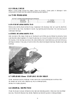
Page 14: ...Check All Fasterner s are tight and intact Safety Chain Guard inspection Safety Decals intact Safety Guards Intact Check Blade wear condition Check Metal Fatigue Clutch Wear Function 6 1 ENGINE Refer to engine manufacturers manual for servicing and maintenance of the engine 6 2 EXCESS CROP BUILD UP Remove all crop deposits from the deck and engine area Build up of crop deposits could result in hea...

Page 15: ...heel by hand and check the wheel alignment To check the bearing try to move the wheel from left to right and feel for any play in the bearings A ensure the wheel locking bolt is tight before you start and follow any jacking procedures If any play is found remove the wheel and inspect bearings Replace any faulty bearings 6 7 GREASING 50mm COUPLING BUSH WEAR Check coupling for signs of damage or wea...

Page 16: ...Ensure mower engine has stopped and the knives have stopped rotating Switch off the fuel tap and let the machine cool down for 5 minutes Disconnect the spark plug cap to ensure the engine cannot be started B Raise the mower to its max cutting height C Carefully raise the drawbar to an incline position so that height adjuster bar at the rear of the mower takes the weight NB Do not attempt this with...

Page 17: ...ctions 1 Remove cover off the belts housing 2 Release the locknut of the tensioner arm 3 Un tighten the belts by turning the tensioning pulley arm Check belts wear and tension regularly Over and under tensioning will cause premature wear of the belts ...

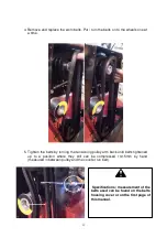
Page 18: ...ts by turning the tensioning pulley arm back until belts tightened up to a position where they still can be compressed 10 15mm by hand measured in between pulley and the counter run belt Specifications measurement of the belts used can be found on the belts housing cover or on the first page of this manual ...

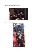
Page 19: ...18 6 Fix the pulley in position with the locknuts 7 Fit the belts housing cover ...

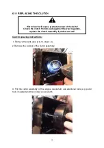
Page 20: ...locknut of the clutch assembly 3 Pull the clutch assembly off the engine crankshaft use additional tools e g puller tool if needed and then install a new clutch Worn clutch will cause premature wear of the belts Check the clutch friction pads against the wear regularly replace the clutch assembly if pads worn out ...

Page 21: ...20 4 Fix the clutch with a locknut 5 Re install the belts see pt 6 10 steps 4 7 For repairs beyond the minor adjustments listed above contact your dealer ...

Page 22: ...sed tugitallad 28 5 Hooldus 29 5 1 Mootor 29 5 2 Kogunenud heina eemaldamine 29 5 3 Visuaalne kontroll 30 5 4 Rehvirõhk 30 5 5 Rootorilaagrite kontroll 30 5 6 Rattalaagrite kontroll 30 5 7 Kinnitusraami kontroll 30 5 8 Üldine ülevaatus 30 5 9 Rootor terade hooldus 31 5 10 Rihma vahetus 32 5 11 Siduri vahetus 35 Varuosade nimekiri 37 Selle sümboliga tähistatakse HOIATUST või ETTEVAATUSABINÕU Nende ...

Page 23: ...takistusi kui mootor töötab Veenduge enne niiduki puhastamist et mootor on seiskunud ja rootor on pöörlemise lõpetanud 14 Ärge kasutage niidukit pimedas v a juhul kui kasutate kunstlikku valgust 15 Ärge kasutage niidukit liigse vibratsiooni esinemise korral peatage niiduk viivitamatult ja kontrollige hooldusgraafikut 16 Ärge ronige niiduki peale 2 OHUTUSJUHISED KOHUSTUSLIKUD TOIMINGUD 1 Järgige mo...

Page 24: ...koolitage kasutajaid enne niiduki käitamist ja kontrollige ohutusreeglite järgimist regulaarselt veenduge enne masina kasutamist et kõik kaitsedetailid on paigaldatud hoidke käed jalad juuksed ja riided kõigist liikuvatest osadest eemal vältige võimalusel avarate rõivaste kandmist hooldage niidukit vastavalt hooldusgraafikule ja ohutusjuhistele Eriti oluline on terade ja kinnitusdetailide hooldus ...

Page 25: ...kaasa tuua kehavigastusi ja seadmete kahjustusi Kui niidukit kasutatakse ATV või kompakttraktoriga peaks kasutaja kandma kõrvaklappe Tavalistes töötingimustes on müratase 83 detsibelli sellise mürataseme juures on kõrvade kaitsmine soovitatav Eespool toodud ohutuskleebised peaksid asetsema teie ATV niiduki peal Kui mõni neist kleebistest puudub teie niidukilt või on kahjustada saanud võtke ühendus...

Page 26: ...iduki tiisli kõrgus võib erineda Kõrguse reguleerimiseks on veotiisli all tõmmits Seda tuleb pikendada või lühendada nii et niiduk asetseks maapinna suhtes horisontaalselt see tagab parema niitmistulemuse KÕRGUSE REGULEERIMINE 1 Vabastage lukustusmutter A 2 Pikendage tõmmitsat et lõikeketta esiosa madalamale lasta või lühendage et lõikeketta esiosa tõsta 3 Kui lõikeketas asetseb maapinna suhtes ho...

Page 27: ... võiks mootorisse sattuda 3 Seadistage drosseli abil mootori õhuklapp ja sobiv tühikäigukiirus 4 Asetage üks jalg niiduki korpuse peale et see oleks kindlas ja tasakaalustatud asendis Tõmmake kindla liigutusega käivitusnööri ja laske nööril aeglaselt korpusesse tagasi kerida mootor peaks käivituma ühe kahe tugeva tõmbe järel 5 Laske mootoril paar sekundit tühikäigul soojeneda viige drossel tehases...

Page 28: ...saavutada paremaid tulemusi Järgige kindlasti allpool toodud juhiseid NORMAALNE LIIKUMISKIIRUS 1 km h väga rasked tingimused 10 km h väga kerged tingimused Niiduki nõuetekohase töö tagamiseks alustage liikumist kõige aeglasemal võimalikul kiirusel ja jälgige et niiduki mootor töötab maksimaalsetel pööretel Kui see ei ole väga keerukate niitmistingimuste tõttu võimalik tõstke terade lõikekõrgust ja...

Page 29: ...l teedel sõita 4 8 RULL TUGIRATTAD Rulli peamine eesmärk on kahjustuste ennetamine Kui ratas vajub auku või rataste vahel on ebatasasusi reguleerib rull niiduki kaalujaotust ja aitab vältida terade lõikumist pinnasesse täiendavad tugitallad aitavad kaitsta rootorit Lisaks aitab rull niita muru äärekivide kõrvalt kuna üks ratas võib üle äärekivi rippuda Rulli ja külgmiste tugirataste tehases seadis...

Page 30: ...haakeseadise pukside kulumise kontroll Kõikide ühendusdetailide seisukorra kontroll Ohutuskleebiste kontroll Ohutusdetailide kontroll Terade kulumise seisukorra kontroll Metallosade kulumise kontroll Siduri kulumise töökorra kontroll 5 1 MOOTOR Teabe mootori teenindamise ja hoolduse kohta leiate mootori kasutusjuhendist 5 2 KOGUNENUD HEINA EEMALDAMINE Eemaldage rootori mootori ja tagarulli ümbruse...

Page 31: ...s rattad jooksevad ühel joonel Laagrite kontrollimiseks proovige ratast vasakult paremale liigutada ja vaadake kas laagrites esineb lõtku Kontrollige eelnevalt kas rattapoldid on kindlalt fikseeritud ja järgige kõiki tungraua kasutamise ohutusreegleid Kui avastate lõtku ühendage ratas lahti ja kontrollige laagreid Vahetage kahjustunud laagrid uute vastu välja 5 7 HAAKESEADISE KONTROLL Kontrollige ...

Page 32: ...lu Terade vahetamiseks või ümberpööramiseks tuleb toimida järgmiselt A veenduge et niiduki mootor on seiskunud ja terad on lõpetanud pöörlemise Sulgege kütusekraan ja laske masinal 5 minutit jahtuda Eemaldage süüteküünal et mootor ei saaks terade vahetamise ajal käivituda B tõstke niiduk maksimaalsesse lõikekõrgusesse C tõstke veotiisel ettevaatlikult kaldasendisse nii et raskus langeb niiduki tag...

Page 33: ...ahetamiseks 1 Eemalda rihmakorpuse kate 2 Keera lukustusmutrid pingutusrullikust eemale 3 Pingutusvarrast keerates lase rihmad lõdvaks Kontrolli regulaarselt rihma pingsust ja kuluvust Üle või alapingutus põhjustavad rihmade kiirema kulumise ...

Page 34: ...maratastele 5 Pinguta rihmad pingutusvarrast keerates Õige rihma pingsus on selline et käsitsi on võimalik ca 10 15mm rihmasid kokku suruda Niidukil kasutatavate rihmade mõõdud leiate rihmakorpusele paigaldatud kleebiselt või käesoleva kasutusjuhendi esimeselt leheküljelt ...

Page 35: ...34 6 Fikseeri pingutusrulliku asend lukustusmutritega 7 Paigalda rihmakorpuse kate ...

Page 36: ...nkt 5 10 sammud 1 4 2 Eemalda siduri lukustuspolt 3 Tõmmake sidur mootori võllilt maha ja paigaldage uus Vajadusel kasutage vastavaid tööriistasid tõmmitsat Kulunud sidur põhjustab rihmade kiiret kulumist Kontrolli regulaarselt siduri klotside kuluvust vajadusel vahetage sidur ...

Page 37: ...36 4 Fikseerige sidur lukustuspoldiga 5 Paigaldage rihmad vt punkt 5 10 sammud 4 7 Kui niiduk vajab suuremat remonti kui ülalkirjeldatud pisitööd võtke ühendust kohaliku edasimüüjaga ...

Page 38: ...37 6 SPARE PARTS VARUOSAD ...

Page 39: ...F390 Gasoline engine 1 19 AT120 104 Adjusting plate L 1 20 AT120 019 Deck weldment 1 21 GB91 86 Split pin 4X28 2 22 AT120 023 Adjusting plate R 1 23 AT120 024 Adjusting plate L 1 24 AT120 026 Blade axle 1 25 AT120 102 Spacer 56 26 AT120 107 Blade 28 27 GB5783 86 Blot M12X80 28 28 EF175 108 Baffle 12 29 EF175 109 Baffle 1 30 AT120 121 Shaft 1 31 AT120 022 Protecting bracket 2 32 UCC207 UCC207 Beari...

Page 40: ... 115 Rubber cover 1 50 GB97 1 85 Plain washer 8 2 51 GB5783 86 Blot M8X25 2 52 GBT278 94 Locking nut M20 2 53 AT120 108 driven belt wheel 1 54 JB T7934Z3 Swellable sleeveREACH 04 35X60 2 55 GB12732 Belt 1067 2 56 GB5783 86 Blot M6X16 7 57 GB93 87 Spring washer 6 7 58 GB97 1 85 Plain washer 6 7 59 AT120 222 Cover plate 1 ...

Page 41: ...GB97 1 85 Plain washer 20 6 7 GB184 86 Locking nut M20 3 8 AT120 215 Bracket for traction 1 9 GB5782 86 Blot M12X80 2 10 GB97 1 85 Plain washer 12 4 11 AT120 030 Hook for traction 1 12 GB184 86 Locking nut M12 2 13 AT120 122 Axle sleeve 2 14 AT120 017 Shaft tube for traction 1 15 GB5782 86 Blot M20X65 2 16 AT120 117 Lifting assembly 1 17 AT120 102 Axle 1 18 GB91 86 Split pin 5X32 2 ...

Page 42: ...41 ...

Page 43: ...earing 51104 1 10 GB70 85 Screw M8x30 1 11 TR200 00 120 Adjusting screw 1 12 MFP120 00 176 Sheath for handle 1 13 MFP120 00 148 Cover for tyre 2 14 GBT278 94 Bearing 80205 4 15 MFP120 00 016 Tyre 2 16 MFP120 00 101 Rubbber cover 4 17 MFP120 00 027 Supporting bracket for tyre 2 18 GB889 86 Nut M10 4 19 GB97 1 85 Plain washer 10 4 20 GB5782 86 Blot M10x65 4 21 MFP120 00 115 Tension spring 2 22 GB578...

Page 44: ...43 ...

Reviews: