background image


888-274-7744 


iQTS244 


www.iqpowertools.com


Repair Manual 

43 

Filter Removal 


1.


Spin the filter knob counterclockwise 
to loosen 


2.


Remove the filter knob 


3.


Remove the filter cover retaining 
screws and remove the cover 

Summary of Contents for iQTS244

Page 1: ...val 43 IQTS244 ASSEMBLY 45 Vacuum Filter Installation 45 Vacuum Suction Installation 47 Vacuum Motor Brushes Installation Early Version 49 Vacuum Brushes Installation New Version 51 Vacuum Motor Installation 53 Support Arm Assembly and Installation 55 Pivot Shaft Mount and Gear Housing Assembly 59 Saw Motor Armature Installation 63 Saw Motor Stator Installation 65 Control Module Installation Early...

Page 2: ......

Page 3: ...888 274 7744 iQTS244 www iqpowertools com Repair Manual 3 IQTS244 DISASSEMBLY Blade Removal 1 Loosen the locking Knob 2 Pull the Lock Pin Knob 3 Raise the Gear Housing ...

Page 4: ...iQTS244 www iqpowertools com Repair Manual 4 4 Lift the Dust Guard 5 Lift the Dust Guard Quick Set so the Dust Guard may be removed 6 With the Dust Guard Quick Set in the UP position lower the Dust Guard and Remove ...

Page 5: ...4 7744 iQTS244 www iqpowertools com Repair Manual 5 7 Loosen the Outer Blade Guard locking knob 8 Lift the Outer Guard up to expose the tile blade 9 Depress the Spindle Lock Button and engage the Spindle Lock ...

Page 6: ...888 274 7744 iQTS244 www iqpowertools com Repair Manual 6 10 loosen hex nut using the wrench provided 11 Remove the blade hex nut and outer blade flange and the blade ...

Page 7: ...4 www iqpowertools com Repair Manual 7 Blade Guard Removal and Disassembly 1 Loosen and remove the Outer Blade Guard retaining screw 2 Remove the outer blade guard cover 3 Remove the Control Module Cover retaining screws ...

Page 8: ...44 www iqpowertools com Repair Manual 8 4 Lift the Control Module Cover to expose the Printed Circuit Board 5 Disconnect the Laser connection 6 Remove the Inner Dust Guard retaining screws and remove the Inner Dust Guard ...

Page 9: ...ng the Blade Guard Dust Seal is the same for the Inner and the Outer Blade Guards NOTE The Dust Seal Plates are specific to the Inner and Outer Blade Guards and are NOT interchangeable 1 Remove the Dust Seal Plate retaining screws 2 Lift and remove the Dust Seal Plate 3 Lift and remove the Dust Seal ...

Page 10: ...888 274 7744 iQTS244 www iqpowertools com Repair Manual 10 ...

Page 11: ...888 274 7744 iQTS244 www iqpowertools com Repair Manual 11 Laser Assembly Removal 1 Remove the Laser Assembly retaining screw 2 The Laser Assembly can be pulled out of the wire channel ...

Page 12: ...888 274 7744 iQTS244 www iqpowertools com Repair Manual 12 ...

Page 13: ...3 Blade Shaft Assembly Removal 1 Remove the Spindle Lock button and compression spring 2 Remove the blade shaft assembly retaining screws 3 Using a flat screwdriver of a small pry bar carefully separate the Blade Shaft Assembly from the Gear Housing Assembly ...

Page 14: ...4 iQTS244 www iqpowertools com Repair Manual 14 4 Remove the Blade Shaft Assembly 5 Check the needle bearing for completeness If required remove the needle bearing using inner bearing puller and slide hammer tool ...

Page 15: ...Move the Control Module Cover to one side to gain access to the Printed Circuit Board 2 Disconnect all the electrical wire connection from the Printed Circuit Board and remove the Printed Circuit Board hold down screw and remove the Printed Circuit Board from the Control Module 3 Remove the Vacuum Power Cord Clamp ...

Page 16: ...744 iQTS244 www iqpowertools com Repair Manual 16 4 Remove the Main Handle top retaining screws 5 Remove the Main Handle Bottom retaining screws 6 Lift the Main Handle Top up and away from the Main Handle Bottom ...

Page 17: ...qpowertools com Repair Manual 17 7 Disconnect all the electrical connection from the switches 8 Route the wire through the Main Handle channel 9 Continue routing the electrical wires through the Control Module channel and remove ...

Page 18: ...powertools com Repair Manual 18 10 Remove the Control Module Base retaining screws 11 Route the saw motor main power and vacuum power cords through the opening at the base of the Control Module and remove the Control Module base ...

Page 19: ...nd Disassembly Newer Version 1 Move the Control Module Cover to one side to gain access to the Printed Circuit Board 2 Disconnect all the electrical wire connection from the On Off Switch and to access the Printed Circuit Board PCB 3 Disconnect the wires from the Printed Circuit Board ...

Page 20: ...888 274 7744 iQTS244 www iqpowertools com Repair Manual 20 4 Remove the Printed Circuit Board retaining screw 5 Remove the Printed Circuit Board 6 Remove the Control Module Base retaining Screw ...

Page 21: ...iQTS244 www iqpowertools com Repair Manual 21 7 Remove the Ground retaining screw 8 Lift the Control Module Base UP and away from the Gear Housing 9 Route the Saw Motor electrical wires thru the Control Module base ...

Page 22: ...888 274 7744 iQTS244 www iqpowertools com Repair Manual 22 ...

Page 23: ...244 www iqpowertools com Repair Manual 23 Saw Motor Removal and Disassembly 1 Remove the Saw Motor Brush Cover 2 Remove the Saw Motor Brush 3 Remove the Saw Motor retaining Screws There is a total of 4 1 at each corner ...

Page 24: ...888 274 7744 iQTS244 www iqpowertools com Repair Manual 24 4 Pull the Saw Motor Cover and Stator away form the gear housing 5 Remove the Armature from the Gear Housing ...

Page 25: ...Stator Disassembly 1 Remove saw motor end cover screws and remove end cover 2 Remove the armature NOTE if the armature is still with the stator Tapping the case against a surface may be required to free the armature from the stator 3 Disconnect saw motor brush connectors ...

Page 26: ...ual 26 4 Route the stator wires through the saw motor housing assembly 5 Loosen and remove the saw motor stator retaining screws 6 Remove the saw motor stator NOTE Tapping the case against a surface may be required to free the stator from the motor case ...

Page 27: ...rtools com Repair Manual 27 Gear Housing Removal and Disassembly 1 Route the Main and Vacuum power cords through the opening in the Gear Housing 2 Loosen and remove the Gear Housing Locking Knob 3 Allow the Gear Housing to open fully ...

Page 28: ...S244 www iqpowertools com Repair Manual 28 4 Remove the Pivot Shaft Mount front retaining screws 5 Remove the Pivot Shaft Mount Rear retaining screws 6 Remove the Gear Housing and Pivot Shaft Mount from the Support Arm ...

Page 29: ...Repair Manual 29 7 Loosen the set Pivot Mount Shaft Set Screw 8 Lay the Gear Housing and Pivot Shaft Mount on its side on a workbench and using a punch and a soft mallet Tap the Pivot Shaft out 9 Remove the Torsion Spring from the Gear Housing ...

Page 30: ...888 274 7744 iQTS244 www iqpowertools com Repair Manual 30 10 Remove the Pivot Shaft 11 Separate the Gear Housing from the Pivot Shaft Mount ...

Page 31: ...74 7744 iQTS244 www iqpowertools com Repair Manual 31 Support Arm Removal and Disassembly 1 Disconnect the Vacuum Power Cord 2 Remove the Support Arm retaining Screws 3 Remove the Support Arm from the Table ...

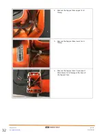
Page 32: ...TS244 www iqpowertools com Repair Manual 32 4 Remove the Support Arm upper Cord Clamp 5 Remove the Support Arm lower Cord Clamp 6 Remove the Support Arm Vacuum and Main Power Cord Clamps at the base of the Support Arm ...

Page 33: ...air Manual 33 7 Using strain relief pliers remove the Main Power cord strain relief 8 Using strain relief pliers remove the Vacuum Power cord strain relief 9 Route the Main and Vacuum Power cord through the Cord Ring at the base of the Support Arm ...

Page 34: ...888 274 7744 iQTS244 www iqpowertools com Repair Manual 34 10 Remove the Cord Ring at the base of the Support Arm ...

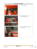
Page 35: ...iQTS244 www iqpowertools com Repair Manual 35 Vacuum Inlet Removal 1 Unlock the Sliding Table 2 Remove the Sliding Table to gain access to the vacuum inlet 3 Loosen the jamb nut while holding the Allen screw secure ...

Page 36: ...888 274 7744 iQTS244 www iqpowertools com Repair Manual 36 4 Unscrew both front and rear allen screws to remove the vacuum inlet suction 5 Remove the jamb nut from the adjustment screw ...

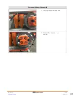
Page 37: ...888 274 7744 iQTS244 www iqpowertools com Repair Manual 37 Vacuum Motor Removal 1 Unplug the vacuum power cord 2 Remove the vacuum retaining screws ...

Page 38: ...888 274 7744 iQTS244 www iqpowertools com Repair Manual 38 ...

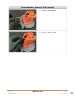
Page 39: ...888 274 7744 iQTS244 www iqpowertools com Repair Manual 39 Vacuum Brushes Removal Early Version 1 Remove the brush end caps 2 Remove the carbon brushes ...

Page 40: ...888 274 7744 iQTS244 www iqpowertools com Repair Manual 40 ...

Page 41: ... iQTS244 www iqpowertools com Repair Manual 41 Vacuum Brushes Removal New Version 1 Remove vacuum motor end cap 2 Lift the brush holders up to gain access to the brushes 3 Remove the brushes from the brush holders ...

Page 42: ...888 274 7744 iQTS244 www iqpowertools com Repair Manual 42 4 Disconnect the brushes and replace ...

Page 43: ...74 7744 iQTS244 www iqpowertools com Repair Manual 43 Filter Removal 1 Spin the filter knob counterclockwise to loosen 2 Remove the filter knob 3 Remove the filter cover retaining screws and remove the cover ...

Page 44: ...888 274 7744 iQTS244 www iqpowertools com Repair Manual 44 4 Remove the filter 5 Remove the Filter tab ...

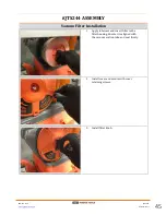
Page 45: ...nual 45 IQTS244 ASSEMBLY Vacuum Filter Installation 1 Apply lubricant and Insert filter in the filter housing Ensure it is aligned with the vacuum suction tube and seat firmly 2 Install cover and secure with cover retaining screws 3 Install filter knob ...

Page 46: ...888 274 7744 iQTS244 www iqpowertools com Repair Manual 46 ...

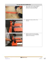
Page 47: ...m Suction Installation 1 Insert adjustment screws and tighten jamb nut on screw until tight but both screw and nut spins freely 2 Install the vacuum suction on the vacuum 3 Adjust vacuum suction and rolling table clearance to 1 32 and tighten jamb nut once achieved ...

Page 48: ...888 274 7744 iQTS244 www iqpowertools com Repair Manual 48 ...

Page 49: ...888 274 7744 iQTS244 www iqpowertools com Repair Manual 49 Vacuum Motor Brushes Installation Early Version 1 Insert the carbon brush in the brush holder 4 Install brush covers ...

Page 50: ...888 274 7744 iQTS244 www iqpowertools com Repair Manual 50 ...

Page 51: ... com Repair Manual 51 Vacuum Brushes Installation New Version 1 Connect the vacuum brush to the connectors and insert into the vacuum brush holders 2 Lower the brush holders up to secure the brushes in place 3 Install the vacuum end cover ...

Page 52: ...888 274 7744 iQTS244 www iqpowertools com Repair Manual 52 ...

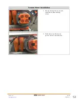
Page 53: ...4 7744 iQTS244 www iqpowertools com Repair Manual 53 Vacuum Motor Installation 1 Mount and align the vacuum and install the vacuum retaining screws 2 Route and secure the vacuum power cord on to the table arm ...

Page 54: ...888 274 7744 iQTS244 www iqpowertools com Repair Manual 54 ...

Page 55: ...5 Support Arm Assembly and Installation 1 Install the Cord Ring at the base of the Support Arm 2 Route the Main and Vacuum Power cord through the Cord Ring at the base of the Support Arm 3 Using strain relief pliers install the Vacuum Power cord strain relief ...

Page 56: ...rtools com Repair Manual 56 4 Using strain relief pliers install the Main Power cord strain relief 5 Install the Support Arm Vacuum and Main Power Cord Clamps at the base of the Support Arm 6 Install the Support Arm lower Cord Clamp ...

Page 57: ...8 274 7744 iQTS244 www iqpowertools com Repair Manual 57 7 Install the Support Arm upper Cord Clamp 8 Install the Support Arm from the Table 9 Secure the Support Arm to the table with the retaining Screws ...

Page 58: ...888 274 7744 iQTS244 www iqpowertools com Repair Manual 58 ...

Page 59: ...epair Manual 59 Pivot Shaft Mount and Gear Housing Assembly 1 Insert the Gear Housing into the Pivot Shaft Mount 2 Slide the Pivot Shaft partially allowing the installation of the torsion spring 3 install the Torsion Spring into the Gear Housing ...

Page 60: ... 60 4 Lay the Gear Housing and Pivot Shaft Mount on its side on a workbench and using a punch and a soft mallet Tap the Pivot Shaft into place 5 Tighten the set Pivot Mount Shaft Set Screw 6 Mount the Gear Housing and Pivot Shaft Mount from the Support Arm ...

Page 61: ... iqpowertools com Repair Manual 61 7 Install the Pivot Shaft Mount Rear retaining screws 8 Install the Pivot Shaft Mount front retaining screws 9 Route the vacuum power cord thru the rear opening on the top of the support arm ...

Page 62: ... 274 7744 iQTS244 www iqpowertools com Repair Manual 62 10 Route the main power cord thru the front opening on the top of the support arm 11 Lower the Gear housing and install the Gear Housing Locking Knob ...

Page 63: ...44 iQTS244 www iqpowertools com Repair Manual 63 Saw Motor Armature Installation 1 Apply general purpose grease on the armature output shaft end 2 Insert the armature into the coupling opening on the support arm ...

Page 64: ...888 274 7744 iQTS244 www iqpowertools com Repair Manual 64 ...

Page 65: ...epair Manual 65 Saw Motor Stator Installation 1 Carefully slide the saw motor stator into the saw motor housing 2 Secure the stator to the saw motor housing with the retaining screws 3 Route the conductors through the saw motor housing assembly ...

Page 66: ...qpowertools com Repair Manual 66 4 Slide the motor over the armature so its flush against the support arm 5 Secure the saw motor housing assembly on to the gear housing with screws on all corners 6 Install the saw motor brushes ...

Page 67: ...888 274 7744 iQTS244 www iqpowertools com Repair Manual 67 7 Install motor brush end cap and tighten DO NOT OVER TIGHTEN ...

Page 68: ...888 274 7744 iQTS244 www iqpowertools com Repair Manual 68 ...

Page 69: ...rly Version 1 Route the saw motor main power and vacuum power cords through the opening at the base of the Control Module and remove the Control Module base 2 Secure the Control Module Base using the retaining screws 3 Continue routing the electrical wires through the Control Module channel ...

Page 70: ...iQTS244 www iqpowertools com Repair Manual 70 4 Route the wire through the Main Handle channel 5 Connect all the electrical connection on to the switches 6 Lower the Main Handle Top down on to the Main Handle Bottom ...

Page 71: ...888 274 7744 iQTS244 www iqpowertools com Repair Manual 71 7 Install the Main Handle Bottom retaining screws 8 Install the Main Handle top retaining screws 9 Install the Vacuum Power Cord Clamp ...

Page 72: ...4 7744 iQTS244 www iqpowertools com Repair Manual 72 10 Install the Circuit Board and connect all electrical connections using the correct electrical diagram 11 Connect all connections on to the On Off Switch ...

Page 73: ...trol Module Installation Newer Version 1 Route the saw motor main and vacuum power cords through the opening at the base of the Control Module and remove the Control Module base 2 Secure the Control Module Base using the retaining screws 3 Install the Ground wires ...

Page 74: ...the Circuit Board and connect all electrical connections using the correct electrical diagram 5 Make the electrical connection on the Printed Circuit Board 6 Make the electrical connections on the On Off switch 7 Install the Module Cover and secure with retaining screws ...

Page 75: ...TS244 www iqpowertools com Repair Manual 75 Blade Shaft Arbor Assembly Installation 1 Insert Lock Guide 2 Apply Multi Purpose Lithium grease in the gear cavities 3 Install the Blade Shaft Assembly in the Gear Housing ...

Page 76: ...888 274 7744 iQTS244 www iqpowertools com Repair Manual 76 4 Install the Spindle Lock button and compression spring 5 Remove the blade shaft assembly retaining screws ...

Page 77: ...s com Repair Manual 77 Blade Guard Assembly and Installation 1 Route the laser wire in the channel and seal with silicon 2 Place the laser assembly in the space provided in the inner blade guard and secure loosely with the retaining screw ...

Page 78: ...888 274 7744 iQTS244 www iqpowertools com Repair Manual 78 ...

Page 79: ...r Manual 79 Blade Guard Dust Seal Installation 1 Place the rubber dust seal on inner dust guard Repeat for the outer Blade Guard 2 Place the seal plate on top of the rubber dust seal and secure with retaining screws Repeat for the outer Blade Guard ...

Page 80: ...888 274 7744 iQTS244 www iqpowertools com Repair Manual 80 ...

Page 81: ...4 www iqpowertools com Repair Manual 81 Blade Guard Installation 1 Attach the inner dust guard on to the support arm with retaining screw 2 Connect the Laser connection 3 Secure Control Module Cover with retaining screws ...

Page 82: ...888 274 7744 iQTS244 www iqpowertools com Repair Manual 82 ...

Page 83: ...ertools com Repair Manual 83 Blade Installation 1 Install the blade 2 Install the hex nut and tighten using the wrench provided 3 Depress the Spindle Lock Button and engage the Spindle Lock to prevent the blade from rotating freely ...

Page 84: ...888 274 7744 iQTS244 www iqpowertools com Repair Manual 84 4 Install the Outer Guard up to expose the tile blade 5 Lower the Outer Blade Guard and tighten the locking knob ...

Page 85: ...85 IQTS244 ADJUSTMENTS Sliding Table Lower and Upper Rollers Adjustments 1 Remove the sliding table from the track and lay it on the stand with the rollers facing up 2 Clean the rolling table wheels with Scotch Brite 3 Clean the table track with Scotch Brite ...

Page 86: ...744 iQTS244 www iqpowertools com Repair Manual 86 4 Wipe the table track with a lightly damp cloth 5 Insert the sliding table back into the stand 6 Check the table for stability by depressing all four 4 corners ...

Page 87: ...44 www iqpowertools com Repair Manual 87 7 Push the sliding table to the forward mechanical stops 8 Depress the area still supported by the table track to check for wobble 9 Pull the sliding table back to the table stop ...

Page 88: ...lling table and place it on the stand with the rollers facing up with the front POINTY END of the table on the right side 12 Place the long side of a square in the valley of the larger lower guide rollers 13 Verify all three 3 lower guide rollers are on the same plane by placing straight edge in the valley of all three 3 lower guide rollers and moving the straight edge back and forth Verify all th...

Page 89: ...st the eccentric to raise or lower the center lower guide roller as needed 16 Verify all three 3 lower guide rollers are on the same plane by placing straight edge in the valley of all three 3 lower guide rollers and moving the straight edge back and forth Verify all three 3 lower guide rollers rotate simultaneously Repeat previous step until satisfied 17 Flip the rolling table so the front POINTY...

Page 90: ...ers since the rolling table is upside down 19 Loosen All three 3 lower guide rollers so the eccentrics may be adjusted and the wheel hold its position 20 Adjust each lower roller so the lower guide roller is at its lowest position when the table is installed in the saw stand 21 Verify all three 3 lower guide rollers are on the same plane Repeat previous step until satisfied ...

Page 91: ...ide roller spins freely the eccentric will need to be adjusted up If the upper guide roller does not turn the eccentric will need to be adjusted down The upper guide roller should contact the upper end of the channel with slight friction for proper adjustment REPEAT for ALL Six 6 sliding table upper rollers 24 Push the sliding table forward to the mechanical stop and check adjustment by depressing...

Page 92: ...l 92 25 Pull the sliding table back to the table stop and check adjustment by depressing rear section of the table Play should be very minimal 26 Remove the table and tighten all six 6 upper guide wheels making sure the eccentric stays in the same position ...

Page 93: ...nd rolling table on the LEFT side of the stand Verify the distance is consistent from front to back of the sliding table IF Adjustments are required GOTO Steip 28 If NO Adjustments are required GOTO Pivot Arm Squareness Check 2 Loosen all six retaining screws that secure the rail to the stand 3 Insert the short arm of a square into the gap between the stand and the sliding table ...

Page 94: ...ubber mallet while the square is still in place to ensure the rolling table is parallel with the stand 5 Tighten the inner most retaining screws for the rail to the stand starting with the retaining screw just behind the vacuum motor 6 Then tighten the screw just in front of the vacuum motor ...

Page 95: ...m Repair Manual 95 7 Then tighten the screw just behind the first screw tightened 8 Then tighten the screw in front of the second crew tightened 9 Push the sliding table forward so the front lower guide wheel is on the edge of the rail guide ...

Page 96: ... iqpowertools com Repair Manual 96 10 Tighten the retaining screw on the front edge 11 Pull the sliding table back so the rear lower guide wheel is on the edge of the rail guide 12 Tighten the retaining screw on the back edge ...

Page 97: ...888 274 7744 iQTS244 www iqpowertools com Repair Manual 97 13 Re Check the gap on the left side by rolling the table back and forth ...

Page 98: ...888 274 7744 iQTS244 www iqpowertools com Repair Manual 98 ...

Page 99: ...heck 1 Remove the dust guard from the blade guard 2 Lower and lock the cutting arm in the down position 3 Place the inside edge of the long arm of the square against the edge of the saw blade and the outer edge of the short arm of the square along the back fence of the sliding table ...

Page 100: ...on the corner of the sliding table fence The gap should be less than 1 64 inch or 016 inches or 0 4 millimeter 5 Flip the square so that it is on the 6 Check the gap on the corner of the sliding table fence The gap should be less than 1 64 inches or 016 inches or 0 4 millimeter ...

Page 101: ...888 274 7744 iQTS244 www iqpowertools com Repair Manual 101 7 Verify the blade has proper clearance on both sides of the channel ...

Page 102: ...888 274 7744 iQTS244 www iqpowertools com Repair Manual 102 ...

Page 103: ...n Clearance Check and Adjustment 1 Check sliding table and vacuum intake where the table first enters 2 Adjust so that gap between table and vacuum suction is about 1 32 inch or 03125 inch or 79375 millimeter 3 It should appear as though the sliding table and the vacuum suction are touching ...

Page 104: ...crew 5 Adjust the vacuum suction set screw until the gap between the sliding table and the vacuum suction is 1 32 6 Push and pull the sliding table back and fourth to check for smoothness Make necessary adjustments 7 Tighten final setting on both screws by holding the set jamb nut and tightening the set screw ...

Page 105: ...owertools com Repair Manual 105 Laser Check and Adjustments 1 Turn laser on 2 Verify the laser beam runs along the center of the louvers on the sliding table 3 If the laser is not straight loosen the laser adjustment locking screw ...

Page 106: ...4 Rotate the adjustment screw on the top of the laser assembly until straight 5 Tighten the laser adjustment locking screw 6 If the laser beam is does not fun along the center of the louvers loosen the retaining screw securing the laser to the inner blade guard ...

Page 107: ...88 274 7744 iQTS244 www iqpowertools com Repair Manual 107 7 Adjust the laser left to right as needed to align the laser beam 8 Once the laser beam is at the desired location tighten the retaining screw ...

Page 108: ...888 274 7744 iQTS244 www iqpowertools com Repair Manual 108 ...

Page 109: ...888 274 7744 iQTS244 www iqpowertools com Repair Manual 109 ...

Page 110: ...888 274 7744 iQTS244 www iqpowertools com Repair Manual 110 ...

Page 111: ...888 274 7744 iQTS244 www iqpowertools com Repair Manual 111 ...

Reviews: