background image

E

G

UP

F

H

wall plate fixing screw

SF-73CA180-150-D.qxd  16/05/2005  11:20  Page 6

Summary of Contents for E-614

Page 1: ...4 05 IQ Europe Limited Sandbeck Lane Wetherby LS22 7TW Visit us at www iq europe co uk Installation helpline 0871 717 1100 IQ 73CA180 150 D IQ 73CA180 300 D Security Floodlight E 614 E 616 SF 73CA180 150 D qxd 16 05 2005 11 20 Page 1 ...

Page 2: ...ification ON CONDITION THAT The buyer takes advantage of any return to store scheme operated by the seller from whom it is bought If the product has a defect outside the period of any seller s return to store scheme it should be returned to IQ Europe Limited at Sandbeck Lane Wetherby W Yorks LS22 7TW England at the expense of the buyer together with evidence of the date of purchase it is the respo...

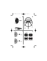
Page 3: ...rom nausea or dizzy spells or on medication with similar side effects If in any doubt consult a qualified tradesperson or electrician SECTION TWO SELECTING THE LOCATION The motion detector has a number of detection zones at various vertical and horizontal angles as shown see diagram A A moving human body needs to cross enter one of these zones to activate the sensor The best all round coverage is ...

Page 4: ...is located onto the wall plate by two lugs which are inserted into the rectangular slots in the top of the wallplate To remove loosen but do not remove the fixing screw and lift the body of the floodlight upwards to release from the wall plate diagram F Mark the position of the fixing holes Ensure wall plate is correctly positioned Note the orientation of the wall plate diagram E Drill the holes I...

Page 5: ...strict RHS detection Restrict LHS detection Restrict long detection Restrict short detection Lens Mask Less sensitive 12m Time TOP VIEW SIDE VIEW 2 5m A 180º Dusk Dimmer Adjustment SF 73CA180 150 D qxd 16 05 2005 11 20 Page 5 ...

Page 6: ...E G UP F H wall plate fixing screw SF 73CA180 150 D qxd 16 05 2005 11 20 Page 6 ...

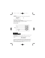
Page 7: ...h the best position for the sensor Switch on the mains power The lamp will immediately illuminate as the unit goes through its warm up period After approximately 1 2 minutes the lamp will extinguish Try to remain outside the detection area during the warm up period CONNECTION Connect the cable to the terminal block on the unit as follows see connection diagram NEUTRAL Blue N EARTH Green Yellow LIV...

Page 8: ...ll now start operating at dusk If you require the light to activate earlier wait until the ambient light level reaches the level of darkness at which you wish the lamp to become operative SLOWLY rotate the control in a clockwise direction until a point is reached where the lamp illuminates Leave the control set at this point At this position the unit should become operative at approximately the sa...

Page 9: ...en 150W or 300W R7S cap floodlight bulb 3 Isolate the mains supply and then unscrew cover screw on the top of the unit 4 Open the glass cover The cover is mounted on hinges and will swing open 5 To remove existing bulb depress then lift one end of the bulb to remove 6 Install new bulb by inserting one end first and depressing gently until enough clearance is gained to seat the other end in the soc...

Page 10: ...nal wall switch Turn OFF the power to the unit and check the wiring connections as per the diagram see previous section 3 Ensure no connections are loose Check the lamp If the lamp has failed replace Ensure that the lamp is seated correctly in the lampholder The level of ambient light in the area may be too bright to allow operation at the current DUSK setting During the hours of darkness adjust t...

Page 11: ...yance over lighting an area can cause to your immediate neighbours Light pollution caused by incorrectly installing a unit or over lighting an area can be limited by carefully considering the location and position of your unit before installation The light spread on all halogen floodlights can be reduced by angling the floodlight downwards on the mounting bracket This will also concentrate the lig...

Reviews: