background image


Published: 23.05.2008     Revised: 13.09.2019    

*IPT reserves the right to change the construction and design of the products at any time without being 
obliged to change previous models accordingly.                 


AKARYAKIT MALZ. PETROL 

KIMYA SAN. ve TIC. LTD.STI. 


ER 1134Y 

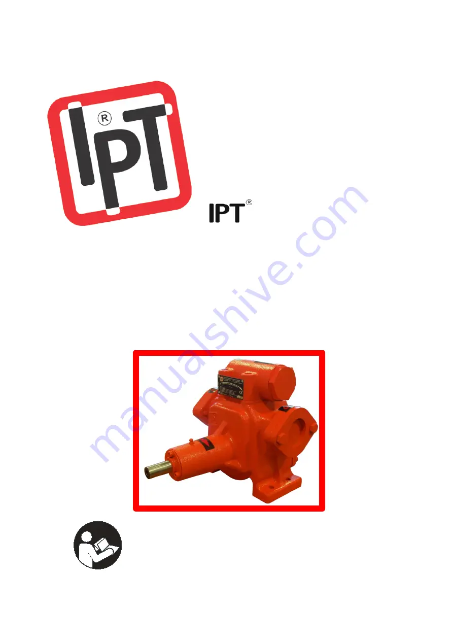
FUEL PUMP 

OPERATION AND MAINTENANCE MANUAL 


DO NOT OPERATE OR MAINTENANCE THE PUMP BEFORE 

READING THIS MANUAL. 


Summary of Contents for ER 1134Y

Page 1: ... construction and design of the products at any time without being obliged to change previous models accordingly AKARYAKIT MALZ PETROL KIMYA SAN ve TIC LTD STI ER 1134Y FUEL PUMP OPERATION AND MAINTENANCE MANUAL DO NOT OPERATE OR MAINTENANCE THE PUMP BEFORE READING THIS MANUAL ...

Page 2: ...without our written permission or if the safety instructions in the instruction manuals are not being followed this declaration becomes invalid Product Eccentric Rotor Driven for ER 1134Y Notified body Bureau Veritas LCIE 33 Avenue du General Leclerc F 92260 Fontenay Aux Roses Certificate number LCIE 08 ATEX 6100 X II 2G c IIC T6 Standards Applicable harmonised standards EN 13463 1 2009 EN 13463 5...

Page 3: ...ation of the pump To obey the operation instructions brings effective operation long pump life and avoid of risks Try to understand the contents Follow the instructions and directions complete and accurate Do not change the operation sequence Keep the manual and its copy near the pump in case the operator can use anytime 1 1 Warnings This manual includes the necessary information as operation main...

Page 4: ...has a 1 diameter of inlet outlet dimensions and 180º inlet and outlet connections Inner mechanism consist of cast iron parts All the dynamic seals gaskets are used to materials made of FKM or teflon in order to give reliable performance in the high petroleum products 1 3 Harmonized Standards Every ER 1134Y pump is designed and is being produced appropriate to the following standards TS 6769 1 Mete...

Page 5: ...he rubber material setting between two stable mechanical parts to prevent leakage and impermeability 1 5 Technical Specifications Type Being in different center points telescopic with two parts turning in same direction Inlet Outlet Dia 1 Inlet Outlet Flange Diameter Capacity 140 lt min max Operating Press 6 bar max Operating Temp 20 60ºC Operating Speed up to 1200 rpm Operating Principle Eccentri...

Page 6: ...he pump has the necessary background The operator shall explain the personnel s responsibilities and authorities If the operator troubles with some points he she can demand a course from the manufacturer firm As a last word the responsible personel must understand the operating instructions exactly 2 3 Safety Rules The pump designed with high care The original parts and the equipments meet the saf...

Page 7: ...Connections and 4 Operation sections 3 2 Positioning and Connections 3 2 1 Dimensions Figure 2 Pump Dimensions 3 2 2 Connection and Assembly Figure 3 Top View of Pump The connection of pump to base is done from the bottom of the pump with 4 x M10 screws A permanent installation will not only reduce the noise and vibration but also increase the performance of the pump In permanent installations it ...

Page 8: ...nd outlet of the pump must be chosen correctly before the installation THE FLANGE COUPLINGS MUST BE DONE BY THE EXPERT PEOPLE Be sure the flanges are parallel before connecting them Any deviation in parallelism will cause of a stres on the pump casing You can make the parallelism between the flanges whether aligning the tube system or putting shims between the flange and the tube Do not exceed the...

Page 9: ...distances between the couplings can not be more than 0 127 mm Figure 6c Parallel Alingment Top View Figure 6d Parallel Alignment Side View The wrong alignment between the pump and the motor causes of faster and excessive outwear in the couplings and the bushings of the pump and the motor The figures show the right coupling alignment Figure 7a Right Alignment Top View Figure 7b Right Alignment Side...

Page 10: ...upwards Be sure that the pulleys are in the same direction and the shafts are parallel to each other Use appropriate belt control device for the tension of the belt If there is no controlling device use your thumb for the control Belt Control Periods 1 Control Control after the first 15 minutes of operation 2 Control Control after the first 3 days of operation 3 Control Control after the first 15 ...

Page 11: ...auses of increase in the speed of the pump and the electricity cost Figure 11c Piping Air Pocket It is satisfied that the liquid stays in the pump by setting a check valve in front of the inlet of the pump Thereby the time of the dry running at the beginning of the operation while waiting for the pipes to be filled is minimized Figure 11d Piping Inlet Check Valve The movement of the liquid backwar...

Page 12: ...D DO NOT RUN THE PUMP DRY It isn t necessary to disassembly the casing to change the direction of rotation changing the by pass unit s place is enough The pump will have the same flow rate and pressure for the opposite direction The matter here is to change the direction of rotation means to change the inlet and outlet of the pump The inlet of the pump is going to be the outlet and the outlet of t...

Page 13: ...ds to swallow splashing to eyes to smudge of the body or breathing the vapours of them without taking appropriate precautions may cause of serious traumas or even death Take the necessary safety precautions while working with the hazardous liquids To change the parts or accessories of the pump to use outwear or damaged parts to use liquids or chemical substances inappropriate to inner mechanism of...

Page 14: ...ile the operating the gun valve etc equipments after the pump must not be kept close long durations so the pump must not be exposed to high pressures After the pumping operation the gun valve etc equipment must be closed and the pump must be shut down immediately 4 2 Dry Run The pump should be protected against dry running Otherwise it will expose to unnecessary abbrasion and breaks down Dry runni...

Page 15: ...ention for the safety of the pump The transportation must be done with the pump s package Use double layered corrugated card board The product is folded with the balloon nylon to protect against dust moist and impacts surrounded by the adhesive band The folded product put to a box The banded box is reinforced by a plastic strap The strapped product is ready for the transportation That put in the c...

Page 16: ...xplosion danger exists according to the specification of the liquid The pump consists of rotating parts To insert an organ like finger to these parts without taking safety precautions may cause of woundings or rupturing an organ We recommend you to keep records of the periodic or other controls and maintenances To apply this kind of maintenance procedure will make your pump work in good condition ...

Page 17: ...15 6 2 Disassembly Figure 17 Pump Disassembly ...

Page 18: ...7 1 20 96310004 Mechanical seal left Ø20 1 21 96310005 Mechanical seal right Ø20 1 22 96100067 Shaft cage 1 23 97310006 Key 5x5x25 a form 2 24 12021039 Cage sphero 1 25 12011129 Cage bronze 1 26 96100072 Shaft idler gear 1 27 97030004 Bushing Ø20x20 2 28 12021049 Idler gear 1 29 99300013 O ring viton Ø110x3 1 30 12021029 Back cover 1 31 99930021 Bolt allen m10x30 3 Table 4 Spare Parts Note pointed...

Page 19: ...bolts on the inlet and outlet flanges By this way determine the stress on the pump casing Check all the pipes whether they are supporting effective weight support Fix properly if necessary ANNUALLY Detach the back cover Check the pump well against abrasion and order new spare part if necessary Control the idler and the rotor gaps When the gaps become as three times more than the original or a noti...

Page 20: ...ent all the leakages The pump can not maintain its duty because of air suction This can be tested by closing the beginning of the inlet piping or sending pressured air in the piping system The gauge shows the leakage as decrease in the pressure 04 Control the voltage of the motor Check the rpm value in the marking of the pump versus motor rpm 05 Check the rotor idler bushings and the shaft Change ...

Page 21: ...f the pump the liquid go backs to the fuel tanker and in every start up the pump has to dry run until the liquid flow is supllied If possible make the piping system above the pump level 24 Check the direction of rotation sign stitched on the casing with the motor s direction of rotation Fix the motor electrical connections 25 The by pass unit can not perform its duty because of broken valve or spr...

Page 22: ...al must be prevented through adequate maintenance Operation Manual Electro static discharges Customer should provide earth connections or equipotential bridges in case of indirect risks EN 13463 1 Operation Manual Table 8 Residual Risks 9 GUARANTEE ER 1134Y pumps are guaranteed for 2 two years THE PUMP IS ONLY GUARANTEED IF IT IS OPERATED APPROPRIATE TO THE CLAUSES WRITTEN INSIDE THIS MANUAL THE P...

Page 23: ...on for the repair work In the case of determining with a report by the service station if there isn t a service station by the seller the dealer the agent or the manufacturer orderly that the repair of the product can not be possible the customer claims changing the product to a new one free of charge refund of money or cost discount at the same amount of fault amount The malfunctions result to op...

Page 24: ......

Reviews: