FALCO Instrument User Manual V1.2R
Unrivalled Gas Detect
ion.
Page 18 of 46
ionscience.com
5.
Reconnect the Control Module to the Ribbon Connector and place into position. Replace and tighten the
three retaining bolts.
6.
Screw the Front Cover back on.
7.
Connect and switch on the power supply.
8.
Do an After-Installation Test.
9.
Calibrate the instrument.
After-Installation Test
Do a test of the relay and the 4
–
20 mA systems to check for correct installation and function.
Do a "Bump Test" to verify that the sensors respond correctly to the test gas at the concentrations
programmed for Set Points 1 and 2.
A “Bump Test” does not calibrate the sensors. If the ins
trument does not display the gas concentration given
by the bottle, do a calibration to give the correct readings.
Installation in Zones with Explosive Atmospheres
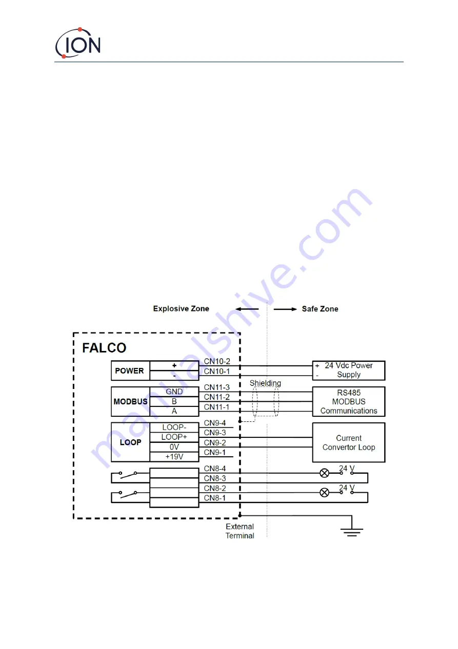
The wiring diagram for the Falco is shown below, that covers in input power, MODBUS and Current Loop.
There are four possible configurations for the 4
–
20 mA current loop depending on the installation site that
are following section.
Figure showing typical connector wiring diagram.
Example method of connection for explosive environment


