


Manual for Installation of
Additional High Voltage Boards to
a C-Pace EP
This manual will show the steps necessary to a High Voltage Boards to a C-Pace EP. The
example pictures show the transition from a two bank to a six bank C-Pace.
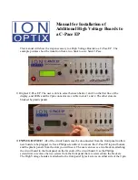
1) Original C-Pace EP. The user is able to select between banks 1 and 2 on the first line of the
display, and LEDs and the 9 pin connector are visible in slots 1 and 2. The other slots are
blocked by plastic panels.
2)
UNPLUG DEVICE!
All of the circuit boards must be unconnected from the front panel to allow
new boards to be plugged in.
Use a Philips screwdriver to remove the C-Pace EP top and bottom
and the plastic panels from the slots you will need. The user can now see two brackets attaching
the circuit board to the front panel on the far ends of the circuit board. Use the Phillips
screwdriver to remove the two screws from the front panel that are screwed into the brackets.
The High Voltage boards are attached to the front panel by jack screws on either side of the 9-pin