


Goodrive350 series high-performance multifunction VFD
Dimension drawings
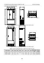
-380-
Appendix C Dimension drawings
C.1 What this chapter contains
This chapter describes the VFD dimension drawings. The dimension unit used in the drawings is
millimeter (mm).
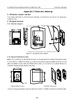
C.2 Keypad structure
C.2.1 Structure diagram
Installation hole dimensions and diagram for key installation without bracket
Outer outline of the keypad
2-M3×8 tapping
screw
Panel
Keypad
1
0
9
.3
71.3
28.5
16.8
2.5
1
0
9
.3
5
6
6
.7
71.3
58
2- ø4
1
9
3
4
.4
19
20.4
Figure C-1 Keypad structure diagram
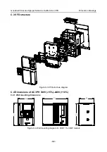
C.2.2 Keypad installation bracket
Note:
You can directly use M3 threaded screws or a keypad bracket to install the keypad externally.
For the 380V 1.5
–75kW VFD models, you need to use optional keypad installation brackets. For the
380V 90
–500kW and the 660V 22–630kW VFD models, you can either use optional brackets or
install the standard keypad brackets externally.
Installation dimensions
Keypad adapter bracket
103
98
1
4
0
1
1
5
4-R12
Figure C-2 Keypad installation bracket (optional) for 380V 1.5
–500kW and 660V 22–630kW models


