background image

21 


2.2 Configuration: 


Note: 

Basic knowledge of the DMX-512 standard is required! 


2.2.1 Construction / installation: 


The "SCANControl" can be used as a desktop device or built into a 19 "rack. 
When installing in a rack, please note that the housing has a built-in fan if possible or that warm air can be drawn 
off  well.  The  device  must  be  screwed  firmly  into  the  rack  with  M6  screws  so  that  it  cannot  slip  during  transport. 
Now connect the power supply to the "SCANControl" and then to the power supply. 
 

2.2.2 Creation of a DMX chain: 


DMX is the abbreviation for Digital Multiplex and enables the digital control of several DMX devices via a common 
control line. 
 
The connections between "SCANControl" and the devices must be made with 2-pin, shielded cables (DMX cable). 
Microphone cables are not suitable for the transmission of DMX digital signals. 3-pin XLR connectors and 
couplings serve as the connection. 
 
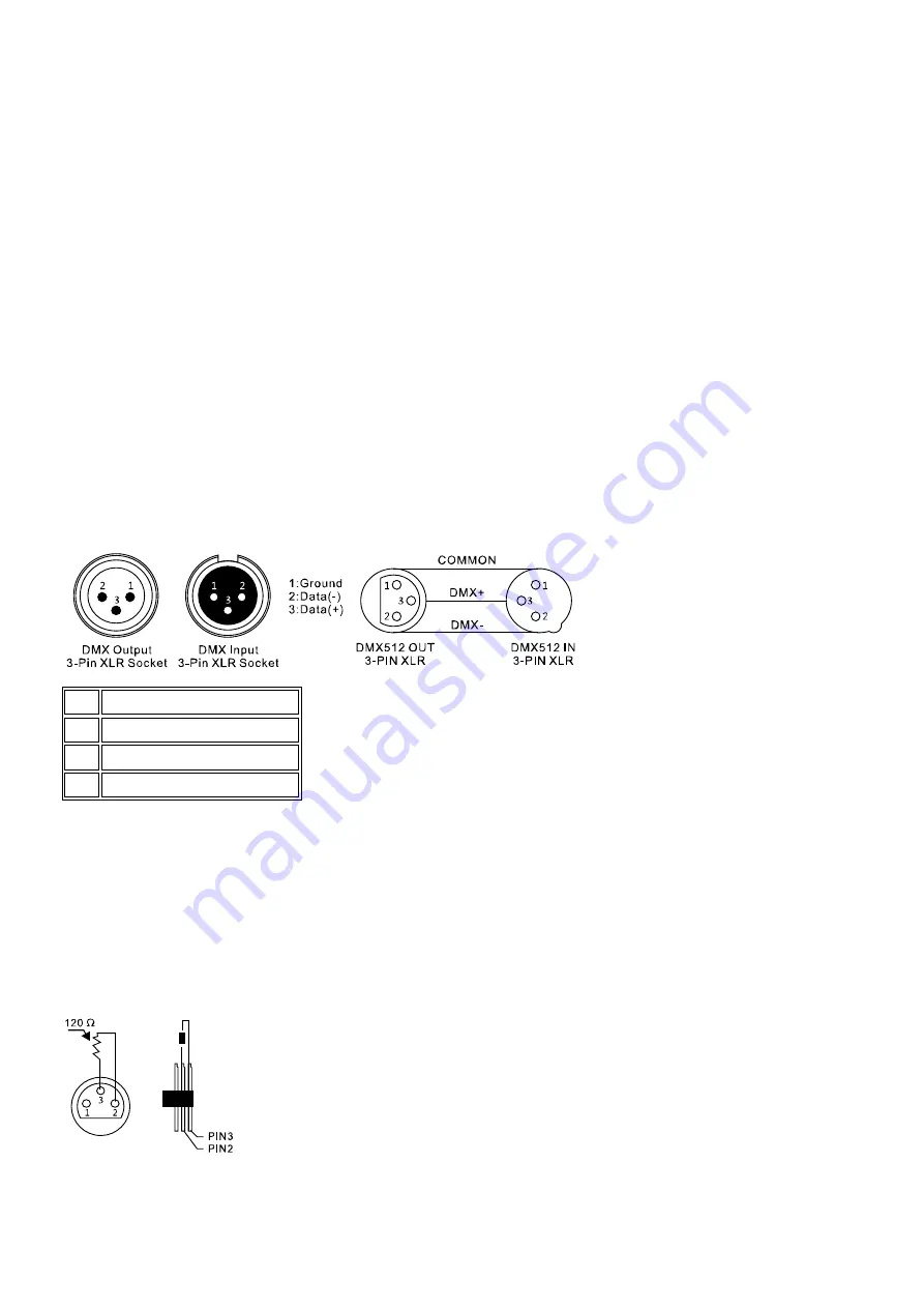
A three-pin XLR socket serves as a DMX output, a three-pin XLR plug serves as a DMX input. 


PIN 

3 pin international 

Ground (shielding) 

Signal inverted (DMX−) 

Signal (DMX +) 

 
Connect the DMX output of the DMX controller to the DMX input of the first DMX device. Connect the output of the 
first DMX device to the input of the second and so on to form a series connection. 
 
From a cable length of 300m or after 32 connected DMX devices, the signal should be amplified with the help of a 
DMX splitter / repeater (e.g. Involight DMXS4, DMXS6 or DMXS8) to ensure error-free data transmission. 
 
IMPORTANT: A terminating resistor should be connected to the last device in a DMX chain at the end of the chain. 
DMX terminators are commercially available, but can also be built yourself. A 120 ohm resistor must be soldered 
into an XLR connector between the two poles (+ and -). 


Summary of Contents for A-000000-05905

Page 1: ...Bedienungsanleitung Manual...

Page 2: ...erung 9 2 3 1 Entwerfen und Speichern eines Programms 9 2 3 2 Abrufen eines Programms 10 2 3 3 berpr fen von einzelnen Szenen 10 2 3 4 Bearbeiten von einzelnen Szenen 10 2 3 5 Kopieren einer Szene 10...

Page 3: ...in die zum Tod oder zu schweren Verletzungen f hrt wenn sie nicht gemieden wird WARNUNG Diese Kombination aus Symbol und Signalwort weist auf eine m glicherweise gef hrliche Situation hin die zum Tod...

Page 4: ...chlag verursachen kann Lieferumfang 1x SCANControl 1x Netzteil 1x Bedienungsanleitung Pr fen Sie bitte ob alle zum Lieferumfang geh rigen Teile tats chlich in der Verpackung sind HINWEIS Das Netzteil...

Page 5: ...sten 1 12 zum An und Abw hlen von Ger ten 2 Die Kontroll LEDs Zeigen an welche Ger te angew hlt sind 3 Tastengruppe SCENES Tasten 1 8 zum Ein und Ausschalten von Beleuchtungsszenen 4 Schieberegler Ein...

Page 6: ...Schieberegler FADE TIME zum Einstellen der berblenddauer beim Abruf von Beleuchtungsszenen oder einer Lauflichtsequenz 22 Taste FINE Umschalten der Aufl sung der PAN und TILT Bewegung Bei aktivierter...

Page 7: ...werden DMX Kabel Mikrofon Kabel sind f r die bertragung von DMX Digitalsignalen nicht geeignet Als Verbindung dienen 3 polige XLR Stecker und Kupplungen Eine dreipolige XLR Buchse dient als DMX Ausgan...

Page 8: ...n Wheel w hlen PAN oder TILT das zugewiesen werden soll Die LED neben dem Rad leuchtet dann 4 W hlen Sie mit den FIXTURES 1 12 Tasten das Ger t dem die Einstellung zugewiesen werden soll 5 Mit der TAP...

Page 9: ...OGRAM Taste gedr ckt bis die Kontroll LED blinkt 2 Die Tasten FINE MODE gleichzeitig dr cken bis die REVERSE LED leuchtet 3 W hlen Sie mit den FIXTURES 1 12 Tasten das Ger t dessen DMX Kanal Invertier...

Page 10: ...ziehen umso h her auch der angezeigte Wert im Display Einige Ger te haben auf einem Kanal mehrere abrufbare Funktionen Beispiel Kanal 1 Wert 0 125 Stroboskop Effekt von langsam bis schnell Wert 126 bi...

Page 11: ...eweiligen SCENES Taster k nnen Sie nun jeden Schritt abfahren lassen und so berpr fen 2 3 4 Bearbeiten von einzelnen Szenen Verschiedene Veranstaltungsorte und Gegebenheiten machen es manchmal erforde...

Page 12: ...sten CHASE 1 6 die zu l schende Sequenz 3 Halten Sie die Taste AUTO DEL gedr ckt und dr cken Sie gleichzeitig die CHASE Taste des zu l schenden Chases Zur Best tigung des Vorgangs blinken alle LEDs de...

Page 13: ...enommenen Musik ab wenn die Buchse nicht angeschlossen ist 1 Dr cken Sie die MUSIC BANK COPY Taste um in MUSIC Betrieb zu schalten 2 Mit den Tasten CHASE 1 bis 6 den gew nschten Chase w hlen 3 Mit dem...

Page 14: ...Data backup Der USB Stick muss mit der USB Buchse verbunden sein 1 Schalten Sie das Ger t aus 2 Halten Sie gleichzeitig die Tasten PAGE SELECT und eine von FIXTURES 1 8 gedr ckt und schalten Sie das...

Page 15: ...le Einwohner der Europ ischen Union Dieses Produkt unterliegt der europ ischen Richtlinie 2002 96 EG Entsorgen Sie Ihr Alt Ger t nicht mit dem normalen Hausm ll Dieses Symbol auf dem Produkt oder der...

Page 16: ...m Informationen ber Gew hrleistungsabwicklungen zu erhalten Verschlei teile werden von der Gew hrleistung nur ber cksichtigt wenn diese bereits bei Auslieferung des Ger tes einen Defekt aufweisen Der...

Page 17: ...ally 24 2 3 Operation and programming 24 2 3 1 To design and save a program 24 2 3 2 Calling up a program 25 2 3 Checking individual scenes 25 2 3 4 Editing individual scenes 25 2 3 5 Copy a scene 25...

Page 18: ...l word indicates an immediately dangerous situation that will result in death or serious injuries if it is not avoided WARNING This combination of symbol and signal word indicates a potentially danger...

Page 19: ...y 1x user manual Please check whether all parts included in the scope of delivery are actually in the packaging NOTE The power supply is in the side padding in a small white box 1 3 Intended use This...

Page 20: ...devices 2 The control LEDs Show which devices are selected 3 Key group SCENES Buttons 1 8 for switching lighting scenes on and off 4 Slider Setting the DMX values for the selected devices The current...

Page 21: ...n when calling up lighting scenes or a chaser sequence 24 PAN TILT setting wheel Switching the resolution of the PAN and TILT movements The control LED lights up when fine resolution is activated 25 M...

Page 22: ...es are not suitable for the transmission of DMX digital signals 3 pin XLR connectors and couplings serve as the connection A three pin XLR socket serves as a DMX output a three pin XLR plug serves as...

Page 23: ...SIGN LED lights up 3 Use the BANK or BANK button to select a wheel PAN or TILT to be assigned The LED next to the wheel then lights up 4 Use the FIXTURES 1 12 buttons to select the device to which the...

Page 24: ...d the PROGRAM button until the control LED flashes 2 Press the FINE MODE buttons simultaneously until the REVERSE LED lights up 3 Use the FIXTURES 1 12 buttons to select the device whose DMX channel i...

Page 25: ...lled up on a channel example channel 1 value 0 125 strobe effect from slow to fast value 126 to 255 dimmer from 0 to 100 Please read in the instructions of your devices to be controlled which DMX chan...

Page 26: ...NK button to select the memory bank you want to edit By pressing the respective SCENES button you can now let each step scene run and thus check it first If a step scene is to be changed carry out ste...

Page 27: ...ed To confirm the process all LEDs on the controller flash three times 2 3 11 Delete all chasers Note If you delete all chasers they will be permanently lost and cannot be called up again The individu...

Page 28: ...the internal microphone if the socket is not connected 1 Press the MUSIC BANK COPY button to switch to MUSIC operation 2 Use the CHASE 1 to 6 buttons to select the desired chase 3 Use the FADE TIME fa...

Page 29: ...he internal memory is saved as a file 2 7 1 Saving data on the USB stick Data backup The USB stick must be connected to the USB socket 1 Turn off the device 2 Simultaneously hold down the PAGE SELECT...

Page 30: ...x 192 x 87mm Weight 2 7kg Part 5 Environmental Protection To all residents of the European Union This product is subject to the European Directive 2002 96 EC Dispose of your old device not with norma...

Page 31: ...the seller for information about warranty processing Wearing parts are only taken into account by the warranty if they already show a defect when the device is delivered The warranty claim does not ex...

Page 32: ...DMX 38 2 2 9 Fade Time 39 2 2 10 Fine 39 2 2 11 39 2 3 39 2 3 1 39 2 3 2 40 2 3 3 40 2 3 4 40 2 3 5 40 2 3 6 40 2 3 7 40 2 3 8 41 2 3 9 CHASE 41 2 3 10 CHASE 41 2 3 11 CHASE 41 2 3 12 Bank Chase 41 2...

Page 33: ...32 INVOLIGHT SCANControl DMX SCANControl 1 1 1...

Page 34: ...33 1 2 230 50 1x SCANControl 1x 1x 1 3 INVOLIGHT SCANControl DMX 512 DC9 12 1000 5 C 45 C INVOLIGHT SCANControl...

Page 35: ...e f r die angew hlten Ger te Der aktuelle DMX Wert wird im Display angezeigt 5 PAGE A A 1 8 6 PAGE B B 9 16 7 PAGE 1 8 9 16 8 PROGRAM 9 MUSIC BANK COPY 10 11 MUSIC MANUAL AUTO 12 BANK 1 23 13 BANK 14...

Page 36: ...FADE TIME 22 FINE PAN TILT 23 REVERSE REVERSE 24 PAN TILT Jogwheel 25 MODE 26 OVERRIDE 27 USB DISK 28 ERROR 29 WORK 2 30 RCA 31 MIDI 5 32 DMX512 3 XLR DMX 33 34 USB USB 35 ON OFF 2 2 c DMX 512 2 2 1 S...

Page 37: ...tal Multiplex DMX512 512 DMX512 DMX XLR DMX OUT DMX IN DMX DMX XLR IN DMX OUT 1 2 DMX 3 DMX 300 DMX 32 DMX Involight DMXS4 DMXS6 DMXS8 DMX DMX DMX XLR 120 2 3 DMX 2 2 3 DMX DMX SCANControl 16 16 16 DM...

Page 38: ...3 BANK BANK PAN TILT 4 SCANNER 1 12 5 TAP DISPLAY 8 16 1 8 9 16 6 MODE SCENES DMX PAN 4 DMX 4 MODE SCENES 4 7 MODE FINE 3 8 PROGRAM 1 PROGRAM 2 2 FINE MODE ASSIGN 3 SCANNER 1 12 DMX PAN DMX 1 TILT DMX...

Page 39: ...MODE SCENES DMX 7 2 MODE FINE 3 8 PROGRAM 2 2 6 1 PROGRAM 2 FINE MODE REVERSE 3 SCANNER 1 12 DMX 4 MODE AUTO DEL 5 2 MODE FINE 3 6 PROGRAM 2 2 7 DMX DMX PAN TLT 1 FINE MODE ASSIGN 2 SCANNER 1 12 DMX...

Page 40: ...SPLY BLACKOUT 2 2 10 Fine FINE 10 2 2 11 SCANNER DMX 8 DMX PAGE SELECT 9 16 DMX 0 255 1 0 125 126 255 0 100 DMX TAPSYNC DISPLAY DMX 0 100 2 3 SCANControl 20 Bank 8 2 3 1 8 4 1 PROGRAM 2 BANK BANK 20 8...

Page 41: ...DEL BLACKOUT 3 SPEED FADE TIME TAP DISPLAY 10 2 3 3 1 PROGRAM 2 BANK BANK 3 SCENES 2 3 4 1 PROGRAM 2 BANK BANK SCENE 3 5 3 SCANNER 4 5 MIDI REC 2 3 5 1 PROGRAM 2 BANK BANK 3 4 BANK BANK 5 MIDI REC SCE...

Page 42: ...OGRAM 2 3 10 CHASE 1 PROGRAM 2 CHASE 1 6 3 AUTO DEL CHASE 3 2 3 11 CHASE CHASE 1 2 AUTO DEL BANK 2 2 3 12 Bank Chase 8 Chase 1 PROGRAM 2 CHASE 1 6 3 BANK BANK 1 20 4 MUSIC BANK COPY MIDI REC 3 2 3 13...

Page 43: ...K COPY MUSIC 2 CHASE 1 6 3 FADE TIME 2 4 Override Override Chase SCANNER OVERRIDE 2 5 Blackout BLACKOUT BLACKOUT Blackout 2 6 MIDI SCANControl MIDI MIDI MIDI MIDI 1 MIDI REC MIDI 01 2 MIDI BANK BANK 3...

Page 44: ...se Chase 120 1 Chase 121 2 Chase 122 3 Chase 123 4 Chase 124 5 Chase 125 6 Chase 126 Blackout 2 7 USB USB 2 7 1 USB USB USB 1 2 PAGE SELECT SCANNER 1 8 USBSAVE1 8 2 7 2 1 2 USB DISK SCANNERS 1 8 USBLO...

Page 45: ...44 4 12 16 8 DMX Jogwheel PAN TILT 160 20 x 8 6 160 Blackout USB 2 x 8 19 DC 9 12V 1000 527 x 192 x 87 2 7 5 2002 96 EC INVOLIGHT 2014 30 LVD 2014 35...

Page 46: ...45 Order code A 000000 05905 www involight com 143406 3 495 565 0161 495 565 0161 105 http www invask ru e mail invask invask ru 143400 20 495 563 8420 495 564 5228 e mail service invask ru...

Reviews: