


54
Optidrive P2 Elevator User Guide V2.30
Parameters
www.InvertekDrives.com
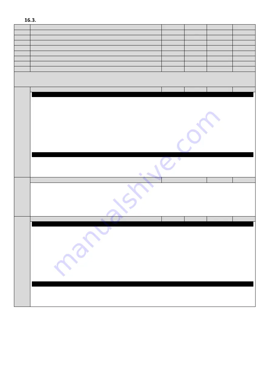
Parameter Group 2 –
Travel Speeds, I/O setup.
Par
Parameter Name
Minimum
Maximum
Default
Units
P2-01
Levelling Speed
0.0
P1-01
5.0
Hz / Rpm
P2-02
High Speed
0.0
P1-01
50.0
Hz / Rpm
P2-03
Intermediate Speed
0.0
P1-01
25.0
Hz / Rpm
P2-04
Inspection Speed
0.0
P1-01
5.0
Hz / Rpm
P2-05
Rescue Mode Speed (400V three phase input drives only)
0.0
*P1-09
5.0
Hz / Rpm
P2-06
High Speed 2
1.0
P1-01
5.0
Hz / Rpm
P2-07
High Speed 3
0.2
5.0
1.0
Hz / Rpm
P2-08
Reserved- Do not use
-
-
-
-
Speeds / Frequencies are selected by digital inputs depending on the setting of P1-13.(see section 6.10.1)
If P1-10 = 0, the values are entered as Hz. If P1-10 > 0, the values are entered as Rpm.
*Limited to 10.0Hz internally.
P2-11
Analog / Digital Output 1 (Terminal 8) Function Select
0
11
1
-
Digital Output Mode. Logic 1 = +24V DC
0: Drive Enabled (Running). Logic 1 when the Optidrive P2 Elevator drive is enabled (Running)
1: Drive Healthy. Logic 1 When no Fault condition exists on the drive. (“inH” is not included as a fault)
2: At Target Frequency (Speed). Logic 1 when the output frequency matches the setpoint frequency
3: Output Frequency > 0.0. Logic 1 when the motor runs above zero speed
4: Output Frequency >= Limit. Logic 1 when the motor speed exceeds the adjustable limit
5: Output Current >= Limit. Logic 1 when the motor current exceeds the adjustable limit
6: Motor Torque >= Limit. Logic when the motor torque exceeds the adjustable limit
7: STO Status. Logic 1 when both STO inputs are present and the drive is able to be operated.
Note: When using settings 4 – 6, parameters P2-16 and P2-17 must be used together to control the behaviour. The output will
switch to Logic 1 when the selected signal exceeds the value programmed in P2-16, and return to Logic 0 when the signal falls
below the value programmed in P2-17.
Analog Output Mode
8: Output Frequency (Motor Speed). 0 to P1-02
9: Output (Motor) Current. 0 to 200% of P1-08
10: Motor Torque. 0 to 200% of motor rated torque
11: Output (Motor) Power. 0 to 200% of drive rated power
P2-12
Analog Output 1 (Terminal 8) Format
See Below
-
= 0 to10V.
= 10 to 0V,
= 0 to 20mA
= 20 to 0mA
= 4 to 20mA
= 20 to 4mA
P2-13
Analog/Digital Output 2 (Terminal 11) Function Select
0
11
0
-
Digital Output Mode. Logic 1 = +24V DC
0: Drive Enabled (Running). Logic 1 when the Optidrive P2 Elevator drive is enabled (Running)
1: Drive Healthy. Logic 1 When no Fault condition exists on the drive (“inH” is not included as a fault)
2: At Target Frequency (Speed). Logic 1 when the output frequency matches the setpoint frequency
3: Output Frequency > 0.0. Logic 1 when the motor runs above zero speed
4: Output Frequency >= Limit. Logic 1 when the motor speed exceeds the adjustable limit
5: Reserved.
6: Rescue Mode Active. Logic 1 when the drive is operating in “Rescue Mode” (Rescue mode is detailed in section 14.2).
7: Analog Input 2 Signal Level >= Limit. Logic when the signal applied to the Analog Input 2 exceeds the adjustable limit
Note: When using settings 4 – 7, parameters P2-16 and P2-17 must be used together to control the behaviour. The output will
switch to Logic 1 when the selected signal exceeds the value programmed in P2-16, and return to Logic 0 when the signal falls
below the value programmed in P2-17.
Analog Output Mode
8: Output Frequency (Motor Speed). 0 to P1-02
9: Output (Motor) Current. 0 to 200% of P1-08
10: Motor Torque. 0 to 200% of motor rated torque
11: Output (Motor) Power. 0 to 150% of drive rated power


