6.
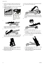
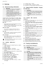
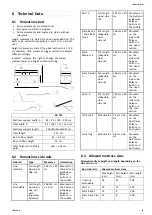
a. Take the hand control.
b. From the upright position (resting on the bed end
attachments); tip the section in over the control
box.
c. Use the hand control to raise the bed until the
square plastic guides on the shear arms connect
with the guideways on the mattress support frame.
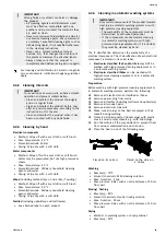
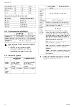
Bed width 85,
90 and 105 cm
The arrow
B
on the
base frame and the
welding point
A
on the
shear arms crossbar,
must be in line.
Bed width 120
B
The welding point
on the base frame
D
and the welding
point
C
on the shear
arms crossbar, must
be in line.
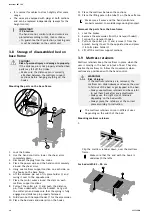
7.
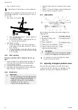
a. Lift up the lower section of the mattress support
up to a horizontal position and hold it there.
b. Lift the upper part of the mattress support slightly
and fit the inserts in the openings of the side tubes.
c. Let the inserts rest in the openings.
8.
Move over to the bed head end.
9.
Lift the upper half of the mattress support and push it
completely in over the inserts.
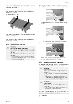
10. Lock the mattress support in the middle:
Bed width 85 and 90:
Push down the seat
section.
Bed width 105 and 120:
Tighten the
finger-screws, under
the side tubes on each
side of the mattress
support.
11. Connect all plugs from the section motors in the
control box.
12. Attach the locking cam over the plugs.
IMPORTANT!
After assembly of the mattress support, check:
– that all plugs (motors and hand controls)
are correctly connected to the control unit
according to the printed symbols.
– that both sections of the mattress support
are completely pushed together and the seat
section completely down (locked).
– that bed ends are correctly attached and that
the mattress support is attached to the shear
arms (snap lock engaged).
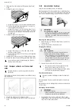
3.5.3 Disassembly of mattress support
Before Disassembly of the bed;
•
Ensure that the castors in the head end of the
bed are pointing towards the center of the
bed.
•
Use the hand control to adjust it to the correct
ergonomic height:
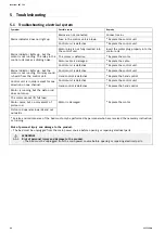
Bed width 85,
90 and 105 cm
The arrow
B
on the base
frame and the welding
point
A
on the shear arms
crossbar, must be in line.
Bed width 120
B
The welding point
on the base frame
D
and
the welding point
C
on
the shear arms crossbar,
must be in line.
1.
Lock the brakes.
2.
Dismount the accessories (bed ends, side rails, lifting
pole etc). Leave the bed end attachments in place.
3.
Disconnect the main power by unplugging it from the
main power socket. On the washable bed (IPx6w) also
remove the power plug from the control box.
1577126-H
11


