


Chapter 5 : Diagnostics
13
3.2.6
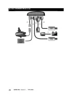
Drive Control Input (DCI) Connections
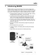
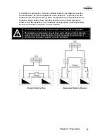
SHARK provides support for an On-board Battery
Charger (OBC), an ‘inhibit’, a ‘speed limit’ and a ‘swivel’
function through the Drive Control Input (DCI) socket as
shown below.
It is recommended that the largest gauge wire
supported by the Shark contacts (16 AWG/1.3 mm
2
) be
used.
Drive Control Input (DCI)
The DCI allows the powerchair speed and configuration
to be adjusted depending on the resistance of the DCI “Loop”. The loop can
be set to be ‘Off’, ‘Normally Open’ or Normally Closed’.
•
Inhibit - Prevents the powerchair from driving, typically when the chair
is being charged, or when a seat is raised or tilted.
•
Speed Limit - Automatically limits the drive speed to a pre-
programmed value, typically when a seat is raised or tilted and driving
too fast may be dangerous. The value to which it slows down is
programmable.
•
Swivel – Automatically swaps the drive motor polarities when the
powerchair swaps (or swivels) between front and rear wheel drive.
When the ‘Active Drive Program’ is set to ‘DCI Input 1+2’, Swivel will
change into a ‘Drive Program Swap’ mode and will automatically swap
from Drive Program 1 to Drive Program 2 whenever the DCI “Swivel” is
active. In this case, the motor polarities will not reverse, unless
specified within the set up of the Drive Program.
To determine the function, an appropriate resistance must be placed across
the DCI Input pin (
I )
and the DCI ground ( - ) pin. Depending on the
resistance value, SHARK will inhibit, limit or swivel driving.
Normal
Speed Limit
Swivel
Speed Limit
Inhibit
Nominal DCI Loop Resistance ( ± 5% )
Resistance
(
Ω
)
0 (>560)*
120
330
120 + 330
(450 nominal)
>560 ( 0 )*
SHARK
Information
Gauge
-
Right GREEN
indicator will
flash
-
Right GREEN
indicator will
flash
Right to left chase
followed by
steady display
Summary of Contents for Hydra C650PW
Page 29: ...29 ...
Page 34: ...7 7 Electromagnetic Compatibility EMC 48 7 8 Contact Details 49 ...
Page 36: ...GBK80260 Issue 1 1 07 2004 2 THIS PAGE IS LEFT BLANK INTENTIONALLY ...
Page 48: ...GBK80260 Issue 1 1 07 2004 14 THIS PAGE IS LEFT BLANK INTENTIONALLY ...
Page 64: ...GBK80260 Issue 1 1 07 2004 30 THIS PAGE IS LEFT BLANK INTENTIONALLY ...
Page 66: ...GBK80260 Issue 1 1 07 2004 32 THIS PAGE IS LEFT BLANK INTENTIONALLY ...
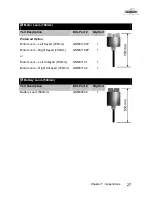
Page 71: ...Chapter 7 Appendices 37 Dynamic SHARK Looms For DK REMA DK PMA Power Module ...
Page 84: ...Installation Manual DK PMA SHARK Power Module by GBK80262 Issue 1 June 2004 ...
Page 87: ......
Page 89: ...GBK80262 Issue 1 1 07 2004 2 THIS PAGE IS LEFT BLANK INTENTIONALLY ...
Page 91: ...GBK80262 Issue 1 1 07 2004 4 THIS PAGE IS LEFT BLANK INTENTIONALLY ...
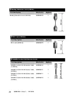
Page 113: ...GBK80262 Issue 1 1 07 2004 26 Dynamic SHARK DK PMA Looms ...
Page 116: ...Chapter 7 Appendices 29 Dynamic SHARK Connector Kits and Adapters ...