background image

Technical Data

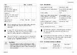
Tyre

Max. pressure

Solid tyre:
305 mm (12”);
515 mm (20”); 560 mm
(22”); 610 mm (24”)

-

-

-

Solid tyre:
150 mm (6”); 140 mm (5”
1/2); 125 mm (5”); 200
mm (8”)

-

-

-

Pneumatic tyre:
200 mm (8”)

2.5 bar

250 kPa

36 psi

The compatibility of the tyres listed above depends
on the configuration and/or model of your
wheelchair.

In case of a tyre puncture consult a suitable
workshop (e.g. bike repair shop, bicycle dealer ...) to
have the tube replaced by a skilled person.

The size of the tyre is mentioned on the sidewall of
the tyre. The change of appropriate tyres must be
carried out by a qualified technician.

CAUTION!

– The tyres pressure have to be equal in both

wheels to avoid a less driving comfort, to keep
the brakes efficiency and an easy propelling of
the wheelchair.

11.3 Materials

Frame/backrest tubes

Aluminum, Steel

Upholstery (seat and backrest)

Foam PUR, Fabric Nylon
and Polyester

Push handles

PVC

Plastic parts like brake handles,
clothes guards, foot plates,
armpads and parts of most
options

Thermoplastic (e.g.
PA, PP, ABS and PUR)
according to marking
on the parts

Folding mechanism / vertical
brace / clamping parts / castor
forks

Aluminum, Steel

Screws, washers and nuts

Steel

All materials used are protected against corrosion.
We use only REACH compliant materials and
components.

Theft and metal detection systems: in seldom cases
the materials used in the wheelchair may activate
theft and metal detection systems.

11.4 Environmental conditions

Storage and

transportation

Operation

Temperature

-20 °C to 40 °C

-5 °C to 40 °C

1608637-E

73

Summary of Contents for Action 4 NG Heavy Duty

Page 1: ...G Action 4 NG Heavy Duty Action 4 NG Comfort en Medium active wheelchair User Manual This manual MUST be given to the user of the product BEFORE using this product this manual MUST be read and saved f...

Page 2: ...duplication or modification in whole or in part is prohibited without prior written permission from Invacare Corporation Trademarks are identified by and All trademarks are owned by or licensed to Inv...

Page 3: ...3 7 3 Armrest height adjustable removable 22 3 7 4 Armrest foldable and removable 23 3 7 5 Armrest height adjustable foldable and removable 24 3 8 Leg rests 24 3 8 1 Swing away leg rests 25 3 8 2 Swi...

Page 4: ...63 8 1 Safety information 63 8 2 Maintenance Schedule 63 8 3 Cleaning and Disinfection 65 8 3 1 General Safety Information 65 8 3 2 Cleaning Intervals 66 8 3 3 Cleaning 66 8 3 4 Disinfection 66 9 Tro...

Page 5: ...information about the product for example product safety notices and product recalls contact your Invacare distributor See addresses at the end of this document In case of a serious incident with the...

Page 6: ...e CE declaration of conformity We are continuously working towards ensuring that the company s impact on the environment locally and globally is reduced to a minimum We only use REACH compliant materi...

Page 7: ...ve into an object head on Drive carefully through narrow passages WARNING Risk due to wheelchair being out of control At high speed you could lose control of your wheelchair and overturn Never exceed...

Page 8: ...ssional for medical advices CAUTION Risk of injury When combining the wheelchair with another device the restrictions of both devices apply for the combination E g the maximum user weight of the devic...

Page 9: ...tion A Manufacturer s address B Date of manufacture C Product description D Seat width E Reference number F Serial number G Medical device H Serial number barcode I EAN HMI barcode J Maximum user weig...

Page 10: ...restraint system straps must be placed in case of transporting the occupied wheelchair in a motor vehicle This symbol is only attached to the wheelchair when it is ordered with the transportation kit...

Page 11: ...on who are propelling the wheelchair themselves frequently The wheelchair is intended for persons ages 12 and up adolescents and adults The weight of the wheelchair occupant must not exceed the maximu...

Page 12: ...Rear wheel with handrim D Parking brake E Front fork with castor F Leg rests swiveling G Footrest H Frame I Seat J Armrest The equipment of your wheelchair may differ from the diagram as each wheelch...

Page 13: ...Do not lean on the parking brakes for support or transfer WARNING Risk of overturning The parking brakes will not operate correctly unless there is sufficient air in the tyres Ensure the correct tyre...

Page 14: ...he wheelchair with a single arm One brake lever right or left hand 3 5 Backrest There are three types of backrest Fixed Folding and Reclining available 3 5 1 Backrest cover You can adjust the tension...

Page 15: ...injury Therefore Invacare strongly recommend the use of anti tippers available as an option when using your back posts with additional load back pack or similar items The height of the backrest cover...

Page 16: ...s with the gas struts version WARNING Risk of injury Always make these adjustments before the user settles down in the wheelchair to prevent injuries Invacare strongly recommends the use of anti tippe...

Page 17: ...are strongly recommend the use of anti tippers available as an option when the backrest is in reclined position WARNING Risk of injury Invacare strongly recommends the use of anti tippers available as...

Page 18: ...away from movable parts and sharp edges to prevent injuries Folding the backbrace 1 Slightly loosen the two hand screws A pull up the backbrace B and swivel it downwards along the backrest on right o...

Page 19: ...atically release when the chair is folded Unfolding the backbrace 1 Fold the backbrace upwards 2 Lock the folding backbrace by pulling the joint A slightly upwards 3 5 8 Push handles IMPORTANT Always...

Page 20: ...ndle to the desired position and tighten the knob again CAUTION If the knob is not correctly tightened the push handle could accidentally come off the backrest tube while pushing it upwards Make sure...

Page 21: ...e the side rests for transportation when carrying the wheelchair up or downstairs CAUTION Risk of pinching Keep your fingers away from movable parts during removing fitting or adjusting the armrest 3...

Page 22: ...d Fitting 1 Push the armrest into the holder Adjusting the height 1 Loosen the screw B with 5 mm Allen key in the groove C of the armrest tube 2 Move the armrest upwards or downwards until you reach t...

Page 23: ...t 1 Loosen the 2 screws of the side protection clamps D 2 Move the side protection upwards or downwards until you reach the desired height 3 Tighten the 2 screws of the side protect clamps D 0 7 1 2 N...

Page 24: ...button B snaps into its armrest socket hole 2 Ensure button protrudes fully through socket hole Rear removing 1 Remove armrest from armrest bracket D by pulling straight up on the armrest Rear fitting...

Page 25: ...leg rests Swinging outwards 1 Activate the release lever A and swing the leg rests to the outside Swinging forwards 1 Swing the leg rest forwards until it engages Unhinging 1 Activate the release leve...

Page 26: ...he knob and the leg rest will lock into the desired position Swinging calf pad and adjustments Swinging calf pad forwards 1 or backwards 2 1 Swing calf pad E forwards 1 2 Pull up the calf pad E and sw...

Page 27: ...th 5 mm Allen key 2 Adjust the depth and angle positions and firmly tighten the fixing screw G 12 Nm or H 8 9 Nm in the desired position Width adjustable foot plates 2 1 Loosen the two fixing screws I...

Page 28: ...directly into the ground thereby curtailing or eliminating its safety function Only use the anti tipper when travelling on even and firm ground IMPORTANT Risk of damage Never step on the anti tipper...

Page 29: ...s and his particular safety limits Make sure that the anti tipper device is fitted correctly on each side if applicable the spring button A and fixation C must be locked into position 3 10 Seat cushio...

Page 30: ...upports 2 Slide the levers D outwards until they are in lock position 3 Firmly tighten the two hand screws A and makes sure that the TWO hand screws A are properly tighten It is recommended that this...

Page 31: ...l with 2 possible side positions of the small handrim The user catches both handrims to propel the wheelchair forward or backwards turns on the LH or RH side by gripping the large or the small handrim...

Page 32: ...r control system left or right hand allows the user with low muscular tone to propel the wheelchair with a single arm The user grips the drive motion lever which propels the wheelchair frontwards or b...

Page 33: ...release the front directional wheel 1 Press the end of the disengaging spring D 2 Release the vertical axle E from its support 3 Reverse the procedure to reinstall 4 5 Posture belt The wheelchair can...

Page 34: ...clasp B 2 To open push the PRESS button C and pull the catch A out of the buckle clasp B Adjusting the length The posture belt has the good length when there s just sufficient space for a flat hand be...

Page 35: ...block B 2 Loosen the handwheel A 3 Adjust the headrest to the desired position 4 Re tighten the handwheel A down to the top of the headrest attachment 5 Slide the stop block B 6 Re tighten the screw I...

Page 36: ...t by a prescribing physician Consult with your provider The lateral positioning pads can be adjusted in height and sideways A B C 1 Remove the backrest cushion A 2 Adjust the lateral positioning pads...

Page 37: ...until you have overcome the obstacle 4 9 Table tray WARNING Risk of tipping injury Max load on the table 8 kg CAUTION Risk of discomfort minor bruises Make sure that the elbows of the user are placed...

Page 38: ...w protrudes from the wheelchair while propelling the wheelchair there is a risk of discomfort or minor bruises CAUTION Risk of pinching fingers There is a mechanism below the half tray where you could...

Page 39: ...t When adjusting the depth of the half tray make sure not to squeeze the stomach of the user Swing away the half tray A 1 The half tray A can be swung away for the front transfer of the user 4 11 Add...

Page 40: ...your wheelchair can affect the rearward stability of your wheelchair This can cause the chair to tip backwards causing injury We strongly recommend the use of anti tippers available as an option when...

Page 41: ...ORTANT Always refer to manufacturer s instruction warning for the usage of the O cylinder The connections of the O cylinder must be installed and set up by a qualified technician dealer A B B B A B 16...

Page 42: ...kg The rod of the drip stand must always be placed in a vertical position i e in a 90 degree angle to the ground no matter the position of the backrest or the wheelchair Height Angle adjustment 1 Loos...

Page 43: ...on the packaging 4 15 Passive illumination You can attach reflectors to the rear wheels 4 16 Cane holder WARNING Risk of overturning Ensure that the cane holder does not project beyond the external d...

Page 44: ...authorized provider will supply your wheelchair ready for use Your provider will explain the main functions and ensure that the wheelchair meets your needs and requirements Adjustments of the axle po...

Page 45: ...Make sure that the front wheels are suitable for the surface you re driving on CAUTION Risk of crushing There may be a very small gap between the rear wheel and the mudguard or armpad with the risk t...

Page 46: ...ied wheelchairs Operate the two brakes simultaneously and do not take slopes exceeding 7 to ensure perfect control of the wheelchair steering Always use the parking brakes to secure the wheelchair dur...

Page 47: ...and on the footrest Never stand on the footrest when getting in and out CAUTION If you disengage or damage the brakes the wheelchair could roll away out of control Do not support yourself on the brake...

Page 48: ...tipping install an antitipper device WARNING Risk of Tipping The wheelchair can tip forwards When setting up your wheelchair test its behavior in terms of tipping forward and adjust your driving style...

Page 49: ...ing backwards Deactivate the anti tipper before going up or down steps or kerbs Going down a step with an assistant 1 Move the wheelchair right up to the kerb and hold the handrims 2 The assistant sho...

Page 50: ...own a step without an assistant WARNING Risk of tipping When going down a step without an assistant you could tip over backwards if you cannot control your wheelchair First learn how to go down a step...

Page 51: ...iating slopes or gradients your wheelchair could tip backwards forwards or sideways Always have an assistant behind the wheelchair when approaching long slopes Avoid lateral slopes Avoid slopes of mor...

Page 52: ...control your direction and particularly your speed 1 Lean back and carefully allow the handrims to run through your hands You should be able to stop the wheelchair at any time by gripping the handrim...

Page 53: ...bend forwards between your knees to pick up something off the floor 1 Point the front wheels forwards To do this move your wheelchair forwards slightly then back again 2 Apply both parking brakes 3 W...

Page 54: ...essive wear and abrasion could affect the strength of load bearing parts Do not pull your wheelchair across abrasive surfaces without the wheels fitted e g pulling the frame over tarmac 7 2 Folding an...

Page 55: ...t the seat surface flattens out 4 Put the wheelchair back completely on the floor and check that the seat edges on both sides are in the guide components 5 If your wheelchair is fitted with an angle a...

Page 56: ...r wheels 1 Release the brakes 2 With one hand hold the wheelchair upright 3 With the other hold the wheel through the external spoke rim around the wheel hub 4 Using your thumb press the removable axl...

Page 57: ...mation on getting and installing an approved and compatible restraint system WARNING If for some reason it is impossible to transfer the wheelchair user to a vehicle seat the wheelchair can be used as...

Page 58: ...ccident collision etc IMPORTANT Refer to the user manuals supplied with the restraint systems The following illustrations may differ depending on the restraint system supplier Securing the wheelchair...

Page 59: ...figure above see location of the attachment labels 2 Attach front straps to the rail system referring to best practice recommended instructions from the safety belt manufacturer 3 Disengage parking br...

Page 60: ...snap hooks are covered with slip resistant material to avoid laterally slipping on the axle IMPORTANT Check the plungers are fully engaged on both sides and located in the same position of the cut ou...

Page 61: ...away from the user s body by parts of the wheelchair such as armrests or wheels etc Ensure the user restraint has a clear path from the user to the anchor point without interference by any part of the...

Page 62: ...re belt of the 3 point passenger restraint system low across the pelvis so that the angle of the posture belt is within the preferred zone A of 30 to 75 to the horizontal A steeper angle is preferred...

Page 63: ...larly or have it carried out by another person weekly monthly annually Check the tyre pressure x Check that rear wheels are seated correctly x Check posture belt x weekly monthly annually Check the fo...

Page 64: ...the footrest seat cover sides backrest frame seat module 2 Tighten any loose bolts with the suitable torque Therefore refer to the Service Manual available on the internet at www invacare eu com IMPO...

Page 65: ...a bicycle tyre lever When doing this check all the way round to ensure that the inner tube is not trapped between the tyre and the rim 8 Inflate the tyre to the maximum operating pressure Check that n...

Page 66: ...require tools 2 Wipe down the individual parts using a cloth or soft brush ordinary household cleaning agents pH 6 8 and warm water 3 Rinse the parts with warm water 4 Thoroughly dry the parts with a...

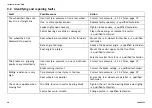
Page 67: ...how to identify and repair faults Some of the actions listed must be carried out by a qualified technician These are indicated We recommend that all adjustments are carried out by a qualified technic...

Page 68: ...arge Reduce the backrest angle qualified technician Seat angle too large Mount the castor upper on the front fork qualified technician Select a smaller front fork qualified technician Incorrect tyre p...

Page 69: ...ck Bearings are dirty or faulty Clean the bearings or replace the castor qualified technician The wheelchair is very difficult to unfold Backrest cover is too tight Loosen the hook and loop strips of...

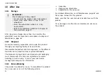
Page 70: ...life Disassemble the product and its components so the different materials can be separated and recycled individually The disposal and recycling of used products and packaging must comply with the la...

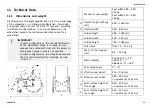
Page 71: ...s not possible In some configurations the wheelchair exceeds the size recommended for travelling by train in the EU Maximum user weight Seat width 385 560 125 kg Seat width 510 620 160 kg A Overall le...

Page 72: ...mm Minimum turning radius 790 mm Stowage width 260 305 mm Stowage height 605 880 mm Stowage length 1050 1150 mm K Overall length without leg rests 390 535 mm L Overall height 795 1050 mm Pivot width 1...

Page 73: ...ving comfort to keep the brakes efficiency and an easy propelling of the wheelchair 11 3 Materials Frame backrest tubes Aluminum Steel Upholstery seat and backrest Foam PUR Fabric Nylon and Polyester...

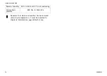
Page 74: ...humidity 20 to 90 at 30 C not condensing Atmospheric pressure 800 hPa to 1060 hPa Be aware that when a wheelchair has been stored under low temperatures it must be adjusted to chapter 8 Maintenance pa...

Page 75: ...Notes...
Page 76: ...eatown Business Campus Seatown Road Swords County Dublin Tel 353 1 810 7084 Fax 353 1 810 7085 ireland invacare com www invacare ie Asia Invacare Asia Ltd 1 Lenton Place North Rocks NSW 2151 Australia...

Reviews: