background image

Intesis

Box

®


ASCII Server 

– KNX


User Manual r1.0 EN


© Intesis Software S.L.U. - All rights reserved 

IntesisBox


is a registered trademark of Intesis Software SLU


11/20


email

[email protected]


web

www.intesisbox.com 


phone: +34 938047134


Connections 

 
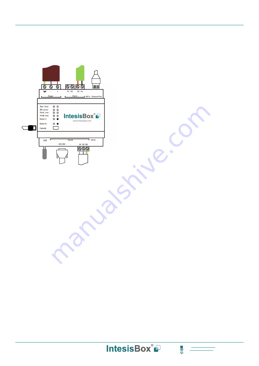
Find below information regarding the IntesisBox connections available. 
 

Power Supply


Must use NEC Class 2 or Limited Power Source (LPS) and SELV


rated power supply. 
 

If using DC power supply: 

Respect  polarity  applied  of  terminals  (+)  and  (-).  Be 
sure  the  voltage  applied  is  within  the  range  admitted 
(check  table  below).  The  power  supply  can  be 
connected  to  earth  but  only  through  the  negative 
terminal, never through the positive terminal. 


If using AC power supply: 

Make sure the voltage applied is of the value admitted 
(24 Vac). Do not connect any of the terminals of the AC 
power supply to earth, and make sure the same power 
supply is not supplying any other device. 

 
Ethernet / ASCII IP 
Connect the cable coming from the IP network to the connector 
ETH  of  the  gateway.  Use  an  Ethernet  CAT5  cable.  If 
communicating  through  the  LAN  of  the  building,  contact  the 
network administrator and make sure traffic on the port used is 
allowed  through  all  the  LAN  path  (check  the  gateway  user 
manual  for  more  information).  With  factory  settings,  after 
powering up the gateway, DHCP will be enabled for 30 seconds. 
After that time, if no IP is provided by a DHCP server, the default 

IP 192.168.100.246 will be set. 
 
PortA / KNX 
Connect the KNX TP1 bus to connectors A3 (+) and A4 (-

) of gateway’s PortA. Respect the polarity  

 
PortB / ASCII Serial 
Connect the EIA485 bus to connectors B1 (B+), B2 (A-

) and B3 (SNGD) of gateway’s PortB. Respect the polarity. 

Connect the serial cable E

IA232 coming from the external serial device to the EIA232 connector of gateway’s PortB. 

This is a DB9 male (DTE) connector in which only the lines TX, RX and GND are used. Respect the maximum distance 
of 15 meters. 
 

Note: Remember the characteristics of the standard EIA485 bus: maximum distance of 1200 meters, maximum 
32 devices connected to the bus, and in each end of the bus it must be a termination resistor of 120 Ω. The port 
includes a DIP-Switch for configuration of biasing circuit as well as termination: 


SW1:  

ON: 

120 Ω termination active  

OFF: 

120 Ω termination inactive (default) 

SW2-3:  

ON: Polarization active 
OFF: Polarization inactive 

 
If the gateway is installed in one bus end make sure that termination is active. 
 
Console Port
 
Connect a mini-type B USB cable from your computer to the gateway to allow communication between the Configuration 
Software  and  the  gateway.  Remember  that  Ethernet  connection  is  also  allowed.  Check  the  user  manual  for  more 
information. 


Power Supply 

Ethernet 
ASCII IP 

USB  
storage 

Console 
Port 

ASCII 
EIA485 
 

ASCII 
EIA232 
 

KNX 

Summary of Contents for IntesisBox ASCII

Page 1: ...IntesisBox ASCII Server KNX User Manual r1 0 EN Issue date 03 2019...

Page 2: ...se agreement or nondisclosure agreement The software may be used only in accordance with the terms of those agreements No part of this publication may be reproduced stored in a retrieval system or tra...

Page 3: ...tered trademark of Intesis Software SLU 3 20 email info intesisbox com web www intesisbox com phone 34 938047134 Gateway for the integration of KNX installations into ASCII IP or ASCII Serial enabled...

Page 4: ...CII TCP 8 3 4 Address Map 8 3 5 Points definition 8 3 6 ASCII messages 10 4 Connections 11 4 1 Powering the device 12 4 2 Connection to ASCII 12 4 2 1 ASCII TCP IP 12 4 2 2 ASCII Serial 12 4 3 Connect...

Page 5: ...m signals and resources from any system capable to be programmed to read and write simple text messages through EIA232 or EIA485 serial port or Ethernet TCP IP port for example Extron LiteTouch system...

Page 6: ...ages requesting writings of points and acts according to the message received See ASCII interface section for details about this ASCII messages Each KNX group address from the KNX is associated to an...

Page 7: ...termined by the flags configured for the point See details in section 4 2 2 Points definition Every internal datapoint to define has the following KNX properties Property Description Description Descr...

Page 8: ...is not configured to do so then the new value will be available to be polled in any moment from the ASCII enabled device connected to this ASCII interface This behaviour of sending or not through the...

Page 9: ...g to the communication object Function Read Write Read Write KNX communication object flags R T R T W U W U Ri U W Ri U R W Ri T U R W T U W T Spontaneous Determines if any change of value for the poi...

Page 10: ...gateway Character use to indicate that this is a reading message configurable from the configuration tool r Carriage return character HEX 0x0D DEC 13 Message to write a point s value ASCII_String vv r...

Page 11: ...after powering up the gateway DHCP will be enabled for 30 seconds After that time if no IP is provided by a DHCP server the default IP 192 168 100 246 will be set PortA KNX Connect the KNX TP1 bus to...

Page 12: ...communication cable coming from the ASCII network to the port marked as Port B of IntesisBox Connect the EIA485 bus to connectors to connectors B1 B B2 A and B3 SNGD of gateway s PortB Respect the pol...

Page 13: ...gateway Mini USB cable to connect to PC Link to download the configuration tool Product documentation 5 2 IntesisBox MAPS Configuration monitoring tool for IntesisBox ASCII series 5 2 1 Introduction...

Page 14: ...nfigure the connection parameters Three subsets of information are shown in this window General Gateway general parameters ASCII ASCII interface configuration and KNX KNX TP 1 interface configuration...

Page 15: ...aracter to be used to read or write the internal gateway datapoint Port TCP port to be used for the ASCII communication By default it is set to 5000 Keep Alive Time of inactivity before sending a keep...

Page 16: ...to the IntesisBox using the Send button in the Receive Send section 5 2 6 Diagnostic To help integrators in the commissioning tasks and troubleshooting the Configuration Tool offers some specific too...

Page 17: ...U All rights reserved IntesisBox is a registered trademark of Intesis Software SLU 17 20 email info intesisbox com web www intesisbox com phone 34 938047134 Figure 5 6 Diagnostic More information abou...

Page 18: ...ARNING In order to avoid earth loops that can damage IntesisBox and or any other equipment connected to it we strongly recommend The use of DC power supplies floating or with the negative terminal con...

Page 19: ...ded 24VDC Push Button Button A Reserved for future use Button B Reserved for future use Operation Temperature 0 C to 60 C Ethernet 1 x Ethernet 10 100 Mbps RJ45 2 x Ethernet LED port link and activity...

Page 20: ...stered trademark of Intesis Software SLU 20 20 email info intesisbox com web www intesisbox com phone 34 938047134 7 Dimensions Recommended available space for its installation into a cabinet wall or...

Reviews: