/
Steppy 3U Manual
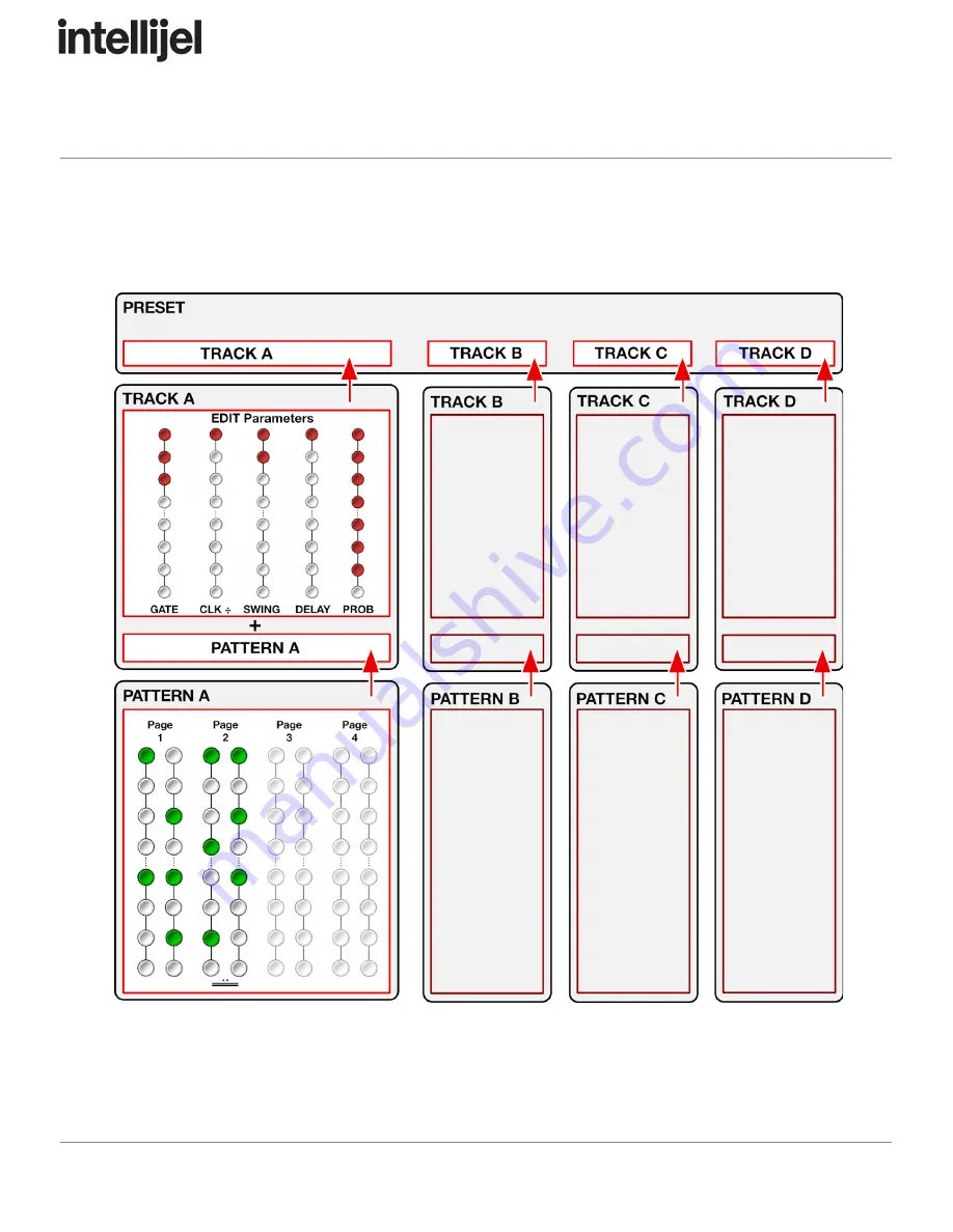
Steppy Architecture
The following diagram illustrates the architecture of a Steppy preset:
Page 33
Page 1: ...Steppy 3U Manual Steppy 3U 4 Track 64 Step Programmable Gate Sequencer Firmware Version 1 2 Manual Revision 2020 03 24...
Page 2: ...set 6 Connect a Clock Program a Track 7 Save the Preset 8 Next Step 8 Front Panel 9 Inputs Outputs 9 Controls 10 Reference 13 Play Mode 13 Select Mode 15 Edit Mode 19 Step Edit Mode 28 Ratcheting 29 T...
Page 3: ...ith the limits for a Class A digital device pursuant to part 15 of the FCC Rules These limits are designed to provide reasonable protection against harmful interference when the equipment is operated...
Page 4: ...e new module To prevent screws or other debris from falling into the case and shorting any electrical contacts do not leave gaps between adjacent modules and cover all unused areas with blank panels S...
Page 5: ...pply check their documentation for instructions Once connected the cabling between the module and power supply should resemble the picture below Before reconnecting power and turning on your modular s...
Page 6: ...d gate will fire when called upon by the pattern Each track can be shifted or rotated forward or backward by a number of steps So if you ve created a pattern that feels like it has its downbeat on ste...
Page 7: ...o load and subsequently clear If a left column button has a solid red light it means a preset is stored in that slot The flashing red button indicates the currently loaded preset If a button isn t lit...
Page 8: ...another module such as a trigger input on a drum module or an envelope In this example we re triggering a kick drum sound on an Intellijel Plonk Each Steppy preset consists of up to four Tracks A B C...
Page 9: ...solid red light it means a preset is already saved in that slot and if you select it you will overwrite that preset The flashing red button indicates the currently loaded preset which you are activel...
Page 10: ...ivider The corresponding LED lights every time it detects an input pulse Note that Steppy will not play without a CLK input NOTE Steppy performs best when driven by a steady clock signal Syncopated ga...
Page 11: ...se backlit button perform different functions depending on Steppy s current mode Play Mode In Play Mode the buttons set and display gate patterns Play Mode is indicated when neither the yellow Select...
Page 12: ...e right column Buttons in the right column immediately to the right of the four Track buttons light YELLOW when the corresponding track is Muted Select Mode is indicated when the yellow Select Mode LE...
Page 13: ...the SELECT button is pressed again to exit Select Mode If pressed and held the SELECT button functions as a momentary switch temporarily putting Steppy into Select Mode while you press the desired MU...
Page 14: ...atched into the CLK input to run and will advance one step for each pulse it receives unless the clock is divided as described later With Steppy in Play Mode and a clock sent to its input Steppy will...
Page 15: ...ode to navigate to the page that contains the desired final step then long press the desired step button For example if you wanted a 32 step pattern hold the SELECT button while you press the PAGE 2 4...
Page 16: ...CT button functions as a toggle button putting Steppy into Select Mode where it remains until the SELECT button is pressed again to exit Select Mode If pressed and held the SELECT button functions as...
Page 17: ...cross multiple pages that is it s longer than 16 steps then activating Page Follow allows Steppy to update its display to follow the page changes NOTE If you re in Select mode and you press a Page but...
Page 18: ...ammed into the pattern but are not within the currently playing loop If Loopy is active pressing two buttons loops playback between those steps inclusive of the buttons you hold So in the far right ex...
Page 19: ...uts Outputs then the button is lit yellow to indicate that Steppy is in RUN mode PANIC feature In Select mode if you long press the RESET button i e hold the RESET button for 1 second you ll send a ga...
Page 20: ...rt press 1 sec this button to put Steppy into Edit Mode The red LED next to the EDIT button turns on when Edit Mode is on Edit Mode uses the right column of multifunction buttons to select which param...
Page 21: ...lse the bottom button makes a gate last the full width of the step allowing for ties Middle values result in steadily increasing gates of fixed length with the shortest gates occurring toward the top...
Page 22: ...ttons sets the actual division with no clock division 1 assigned to the top most button and 64 assigned to the bottom most meaning the sequence advances one step for every 64 CLK input pulses To set t...
Page 23: ...g on the top button to 78 swing on the bottom button To set the Swing amount for the selected track simply press the left column button corresponding to the desired value If you press and hold the val...
Page 24: ...m 0 no delay on the top button to 58 delay on the bottom button To set the Delay amount for the selected track simply press the left column button corresponding to the desired value If you press and h...
Page 25: ...e bottom results in a higher probability that any programmed step will play The bottom button 100 is the default This means your pattern will play exactly as programmed every single time To set a Prob...
Page 26: ...h rapidly the same number of times as the shift amount to confirm the shift has occurred To set a Shift amount for the selected track simply press the left column button corresponding to the desired v...
Page 27: ...one of the 8 buttons in the top row to save the preset to that location 5 All buttons will flash quickly to indicate that the preset has been saved 9 LOAD button When in Edit mode press this button t...
Page 28: ...ed by the left column button corresponding to the preset you want to delete This loads that preset into active memory as indicated by the rapidly flashing button 3 Long press 1 sec the LOAD button All...
Page 29: ...the flashing four buttons to edit the corresponding parameter on a per step basis That button will flash yellow and any steps with a per step edit already assigned to it will light up red The current...
Page 30: ...by pressing any of the column s bottom 7 buttons which correspond to 33 50 66 75 87 5 and 100 probability However if you press the top parameter value 12 5 in this case then the step uses the track s...
Page 31: ...sh to ratchet This puts you into the step s Ratchet Assignment mode If you pressed buttons 1 8 you will then use the right column of buttons to set the number of ratchets If you pressed buttons 9 16 y...
Page 32: ...tton to which you want to paste it 6 When you re done entering or editing ratchets long press 1 sec the EDIT button to exit Step Edit mode The red Edit LED stops blinking and Steppy returns to Play mo...
Page 33: ...on the top left correspond to the four track patterns A B C and D With a CLK signal at the CLK input tap these buttons to record trigger patterns in real time into the corresponding track NOTE You can...
Page 34: ...Steppy 3U Manual Steppy Architecture The following diagram illustrates the architecture of a Steppy preset Page 33...
Page 35: ...wo pages and wish to copy the pattern from the original page to the second page 1 Press the SELECT button to enter Select Mode 2 Hold the button corresponding to the page you want to copy from 1 2 3 o...
Page 36: ...rmware version 2 4 then it would light the second button in the left column and the fourth button in the right column as shown to the right Firmware Change Log 1 20 2020 01 10 NEW FEATURE Latching Loo...
Page 37: ...g is saved across boots On the SELECT page you ll see the SAVE RST button light yellow if RUN mode is enabled This feature is discussed in the RESET RST IN jack description in the Inputs Outputs secti...