Dual ADSR Manual
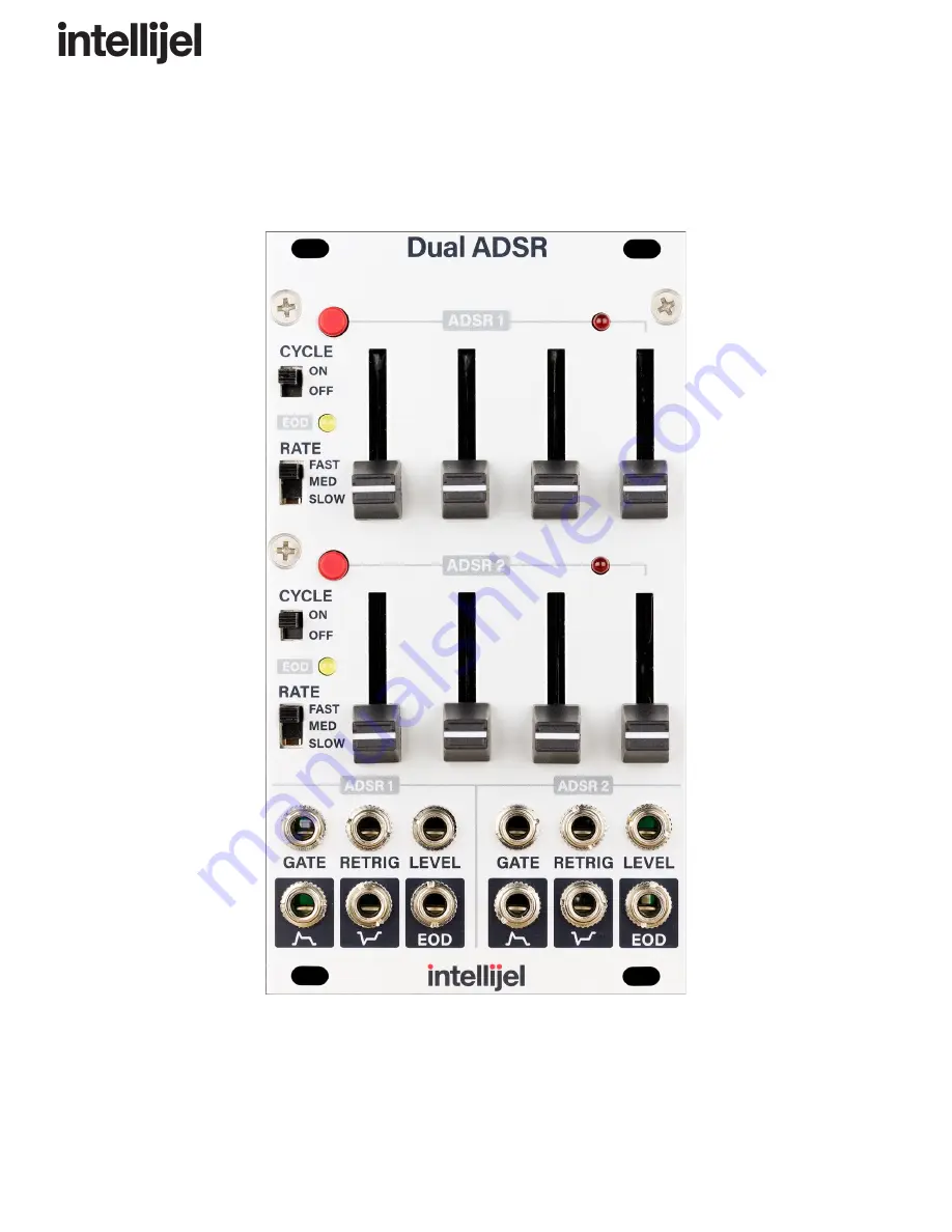
Dual ADSR
Dual Slider-Based ADSR Envelope Generator
Manual Revision: 2018.09.13
Page 1: ...Dual ADSR Manual Dual ADSR Dual Slider Based ADSR Envelope Generator Manual Revision 2018 09 13 ...
Page 2: ...Dual ADSR Manual Table of Contents Table of Contents Compliance Installation Installing Your Module Overview Front Panel Controls Inputs Outputs Envelope Times Technical Specifications Page 1 ...
Page 3: ...ith the limits for a Class A digital device pursuant to part 15 of the FCC Rules These limits are designed to provide reasonable protection against harmful interference when the equipment is operated in a commercial environment This equipment generates uses and can radiate radio frequency energy and if not installed and used in accordance with the instruction manual may cause harmful interference ...
Page 4: ...new module To prevent screws or other debris from falling into the case and shorting any electrical contacts not leave gaps between adjacent modules and cover all unused areas with blank panels Similarly do not use open frames or any other enclosure that exposes the backside of any module or the power distribution board You can use a tool like ModularGrid to assist in your planning Failure to adeq...
Page 5: ...upply check their documentation for instructions Once connected the cabling between the module and power supply should resemble the picture below Before reconnecting power and turning on your modular system double check that the ribbon cable is fully seated on both ends and that all the pins are correctly aligned If the pins are misaligned in any direction or the ribbon is backwards you can cause ...
Page 6: ...he exception of the GATE input Controls 1 GATE BUTTON The gate button is normalled to the GATE input Pressing and holding the button will activate the envelope in the same way as an incoming gate signal from a keyboard or sequencer It provides a useful way to test out the envelope settings or to manually to trigger the envelope during performance 2 CYCLE SWITCH When in the ON position the end of t...
Page 7: ...ongest setting is set with the RATE switch 7 S USTAIN This slider sets the level of the sustain stage It is 0 V at the bottom and 5 V at the top 8 R ELEASE This slider sets the duration of the envelope release stage This is the time it takes the envelope to go from the sustain level back to 0 after the gate is released The length of the longest setting is set with the RATE switch 9 LEVEL INDICATOR...
Page 8: ...erted version of the envelope from 0 to 5 V F EOD This gate output goes high once the envelope completes the decay phase and remains high until the next attack phase Envelope Times MODE MINIMUM ATTACK TIME MAXIMUM ATTACK TIME MINIMUM DECAY RELEASE TIME MAXIMUM DECAY RELEASE TIME Fast 0 2 ms 1 5 s 0 6 ms 2 5 s Medium 1 8 ms 10 s 3 5 ms 10 s Slow 9 3 ms 60 s 30 ms 60 s NOTE Times are approximate and...