Intelleflex CMR-6100 User Manual Download Page 6


User Manual | CMR-6100         


6                                                                    Intelleflex Confidential 

2.4 

Detailed System Specifications 

2.4.1  Antennas 

There are four Reverse Polarity (RP) Threaded Neill-Concelman  (TNC)  connectors  on the CMR-6100. 
These  connectors are separated into pairs, two are dedicated for transmit and two  are  dedicated for 
receive. At a minimum one pair of antennas needs to be connected: a “pair” consisting of one transmit 
antenna and one receive antenna. 
 
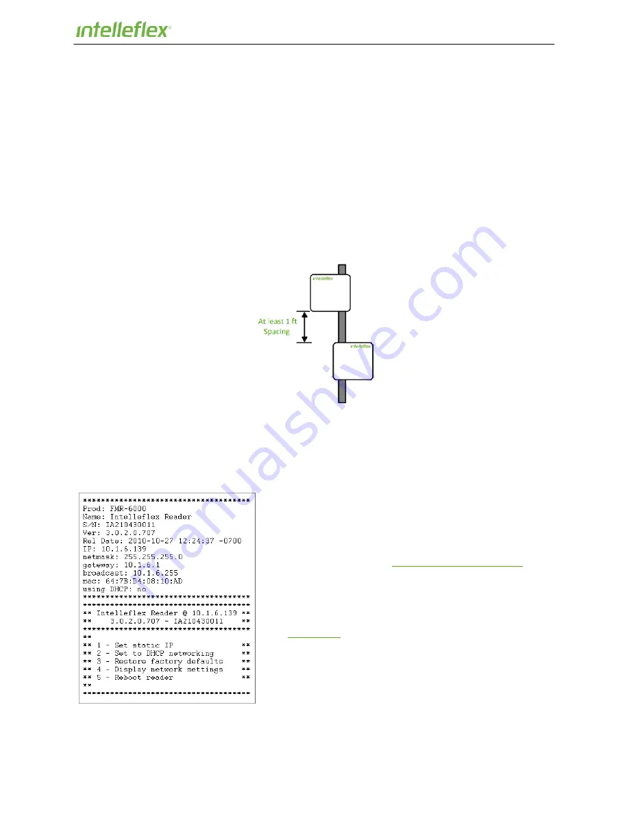
Mounting hardware is provided with the antennas to easily attach antennas either to a pole or wall.  A 
mounting instruction sheet is provided with the  mounting hardware. Mount one antenna pair such that 
antennas are at least six feet above the ground. To maximize read range, space the Transmit (Tx) and 
Receive (Rx) antennas at least a foot apart. You can also mount the antennas side-by-side (horizontally) 
so long as a minimum separation of one foot is maintained. Be sure to verify the antennas are connected 
to the correct ports; the antenna’s function is labeled on the back of the antenna.   
 
Connect the Tx antenna to the Tx port on the reader, and Rx antenna to the Rx port on the reader. Use 
the supplied RF cables with reverse TNC connecters. 


Figure 2.3-1 Tx and Rx antenna spacing 


Two pairs of antenna pairs may be connected to the reader at any given time. When several Rx and Tx 
antennas are connected, the reader can be set up to transmit on any Tx port and receive on any Rx port. 

2.4.2  Serial Connection 

There is a direct serial connection port on the CMR-6100 that 
allows for a PC to establish a connection with the reader 
through a standard USB cable. This creates a Virtual 
Communication Port (VCP) that allows PCs without serial ports 
to connect directly to the reader without buying a Serial to USB 
adapter.  Drivers to support this feature can be found on the 
Intelleflex support website: 

Intelleflex Download Support

. 

 
Once the driver is installed and the USB cable is connected to 
both the reader and the PC,  opening up a serial  connection 
can be done easily on both Windows or OS X for Mac  based 
systems.  To connect over serial on a specific system please 
see 

Appendix A

 for details. Use a Baud Rate of 115200, data 8 

bit, Parity none, and Stop of 1 bit with no flow control.  Once a 
serial connection is established to the reader connect the 
Ethernet cable using the power injector (see next section for 
details). Allow  the unit to boot. When the unit has booted all 
the way, you will see  the print out on the screen as in Figure 
2.3-2. 

Figure 2.3-2 Serial Port Boot Output 


Summary of Contents for CMR-6100

Page 1: ...CMR 6100 User Manual Doc ID TS 34 0512 Published May 29 2012...

Page 2: ...This device complies with part 15 of the FCC Rules Operation is subject to the following two conditions 1 This device may not cause harmful interference and 2 this device must accept any interference...

Page 3: ...Interface 9 3 1 Establishing a Connection 9 3 2 Checking Versions and Status 9 3 3 Manually Setting to Static or DHCP 10 3 4 Upgrading Reader Firmware 11 3 5 Basic Inventory Demo 11 3 6 Basic Memory R...

Page 4: ...communicating to the CMR 6100 and other local devices The CMR 6100 also offers two optically isolated general purpose inputs and two open drain outputs There are two pairs of bi static antenna connec...

Page 5: ...O 18000 6C revision 1 Manchester BAP 25 6 25 sec 8 128 Kbps BLF 80 320 KHz M 2 128 2 5 160 Kbps Performance Transmitter RF Output Power Receiver Sensitivity Frequency Range Number of Channels 0 to 30...

Page 6: ...TNC connecters Figure 2 3 1 Tx and Rx antenna spacing Two pairs of antenna pairs may be connected to the reader at any given time When several Rx and Tx antennas are connected the reader can be set up...

Page 7: ...rom the reader The light will flicker or pulse at a rate that is dependent on the length and duty cycle of the transmission If the reader is assigned to read the full content of user memory the light...

Page 8: ...IO socket that the provided screw terminal fits into The screw header fits securely into the socket and is tightened down with the two attached screws Looking at the reader the pins are numbered left...

Page 9: ...n inventory C3 or C1G2 tag IDs and interact with tag memory 3 1 Establishing a Connection The CMR 6100 reader supports Internet Explorer and Mozilla Firefox For More information about obtaining the IP...

Page 10: ...in Management tags the Reader Name Network Setup and NTP server can be dynamically configured Be sure to talk to your network administrator before assigning a static IP address to the reader as this c...

Page 11: ...rent RF and reader parameters read and write to tag user memory and verify functionality of the system Figure 3 5 1 Inventory and Search Configuration Page Reader parameters are controlled via config...

Page 12: ...the left shows the tag ID of each tag as it is read Text from this window may be copied into a document if needed The window holds the last 100 tag IDs read The summary window on the right displays th...

Page 13: ...in the same way that the EPC memory was accessed here 3 7 GPIO Testing and Verification Page The GPIO Testing page enables the CMR 6100 to either set or detect the logic levels of the general purpose...

Page 14: ...rmat Plug and play architecture allows for easy addition of new message formats see Intelleflex Data Services documentation for more details about message formats Data Buffering If there is no connect...

Page 15: ...User Manual CMR 6100 15 Intelleflex Confidential...

Page 16: ...reader set the following parameters protocol C3 or C1G2 power set full power at 30 dBm Q value set between 4 and 6 select the right Tx and Rx antennas Make sure that the appropriate type of tags are...

Page 17: ...through our web submittal form http www intelleflex com Support sfdcform asp or E mail support intelleflex com If the reader needs to be returned for service please fill out the warranty card include...

Page 18: ...the System Properties window click on the Hardware tab 5 With the Hardware tab selected click on the Device Manager Button For Windows 7 1 Click on Start and then type Device Manager in the search bar...

Page 19: ...ommand Space and type in Terminal Once you have a terminal window open type the following Linux commands Note that they might be slightly different based upon which version of Linux that is running Fi...

Reviews: