


SR2300 2U Server Chassis Technical Product Specification
Revision 1.2
Intel Order Number A94546-004
15
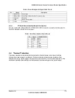
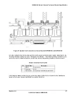
The following table provides the pin-out for the power supply edge connector.
•
Signals that can be defined as low true or high true use the convention:
signal
#= low true
•
Reserved pins are for future use.
•
No Connect (NC) locations must be empty locations on the power supply edge card and
in the mating connector to meet spacing requirements.
Table 4. Edge Connector Pin-out
Descriptio
n
Pin#
Pin# Description
NC B1
A1
NC
AC Neutral
Pre-charge
B2
A2
AC
Neutral
NC B3
A3
NC
AC Line
Pre-charge
B4
A4
AC Line
NC
B5
A5 NC
NC B6
A6
NC
-12V B7
A7
5VSB
PS-ON B8
A8
PSKill
A0 B9
A9
ReturnS
A1 B10
A10
SCL
AC warning B11
A11
SDA
Fail B12
A12
Alert#
PWOK B13
A13
Vbias
12LS B14
A14
+12VS
Ground B15
A15
Present#
Ground B16
A16
+12V
Ground
B17
A17
+12V
Ground B18
A18
+12V
Ground B19
A19
+12V
Ground B20
A20
+12V
Ground B21
A21
+12V
Ground B22
A22
+12V
Ground B23
A23
+12V
Ground B24
A24
+12V
Ground B25
A25
+12V
Ground B26
A26
+12V
Ground B27
A27
+12V
Ground B28
A28
+12V
Ground B29
A29
+12V
Keying Locations
A1
A29
B1
B29
Interior Face
Summary of Contents for SR2300 - FRONT BEZEL BLK
Page 10: ......