background image

Intel® Server System R2600SR Setup and Service Guide


39 


3.9


Replacing the Keyboard/Video/Mouse (KVM) Module  

Installed within the front panel of each compute node (Figure 1, top row, right) is a Keyboard/Video/Mouse 
(KVM) Module, which provides support for one USB 3.0 Port and one KVM Breakout Cable (1 per system). 
When attached to the KVM module, the KVM cable supports one serial port, two USB 2.0 ports, and one VGA 
port.  The combination of the KVM module and cable allows connection of a keyboard, monitor and mouse 
for local console support of an individual compute module. 


Figure 34. KVM module 

3.9.1


Removing the KVM Module 

Complete the following steps to remove a KVM module: 

1.


Turn off the corresponding compute node with the KVM module to be removed. 

2.


Remove the compute node (see Section 3.2.1). 

3.


Remove the compute node cover (see Section 3.2.3). 

4.


Remove the air baffle (see Section 3.3). 


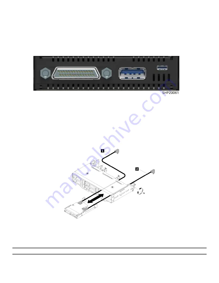
Figure 35. Removing the KVM module  

5.


Loosen the retaining screw on the right side of the compute node. 

6.


Disconnect the long (see Number 1) and short (see Number 2) signal cables from the system board. 

7.


Push the KVM module from the back side of the compute node and slide it out of the node. 

Note: Be careful when routing the cables through the openings in the backplane or the drive bay. 

Summary of Contents for R2600SR Series

Page 1: ...r Products and Solutions Intel Server System R2600SR Product Family Setup and Service Guide A guide providing initial setup instructions and procedures to insert and extract system components Rev 1 1...

Page 2: ...Blank page...

Page 3: ...600SR Setup and Service Guide 3 Document Revision History Date Revision Changes February 2018 1 0 Initial release March 2018 1 1 Added replacement instructions for the PCIe I O Risers and for the Powe...

Page 4: ...s document The products described may contain design defects or errors known as errata which may cause the product to deviate from published specifications Current characterized errata are available o...

Page 5: ...support intel com support motherboards server sb cs 010770 htm Consignes de s curit Lisez attention toutes les consignes de s curit et les mises en garde indiqu es dans ce document avant de suivre tou...

Page 6: ...s of the jumper with the pliers never the wide sides Gripping the wide sides can damage the contacts inside the jumper causing intermittent problems with the function controlled by that jumper Take ca...

Page 7: ...only After removing electronic devices from the system or from their protective packaging place them component side up on to a grounded anti static surface or conductive foam pad Do not place electro...

Page 8: ...Backup 20 2 4 1 Backing Up the System Configuration 20 3 System Service 21 3 1 Compute Node Service Common Procedures 21 3 1 1 Removing the Compute Node 22 3 1 2 Installing the Compute Node 23 3 1 3...

Page 9: ...the System Configuration after System Board Replacement 43 3 11 1 Updating the Universal Unique Identifier UUID 43 3 11 2 Updating Desk Management Interface System Management BIOS DMI SMBIOS Data 45 3...

Page 10: ...the PDM 75 3 18 3 Installing the PDM 75 Appendix A Getting Help 76 Appendix B Glossary 77 List of Figures Figure 1 System front view 10 Figure 2 System back view 11 Figure 3 Compute node detail view 1...

Page 11: ...e 40 Figure 38 KVM cable routing 41 Figure 39 Removing the system fan cover 51 Figure 40 Fan fault LEDs 52 Figure 41 Removing the 60x60x56mm fan 52 Figure 42 Removing the 80x80x80mm2 fan 53 Figure 43...

Page 12: ...70 Figure 66 PIOR right removal 71 Figure 67 PIOR left installation 71 Figure 68 Securing the PIOR left with screws 72 Figure 69 Fan cable connection to the PIOR left 72 Figure 70 PIOR right installat...

Page 13: ...zation of the Intel Server System R2600SR Setup and Service Guide is as follows Introduction Chapter 1 The Introduction chapter provides a high level overview of the Intel Server System R2600SR Produc...

Page 14: ...PCIe Add in Card Getting Help Appendix A Glossary Appendix B 1 4 Resource Information and Software For additional information about the Intel Server System R2600SR product family products or any of th...

Page 15: ...s have been disconnected from the server system Before Setting Up or Servicing the Intel Server System R2600SR Before working with this server product observe the safety and ESD precautions found in t...

Page 16: ...2 1 1 System Front View The Intel Server System R2600SR product family system s four compute nodes are removable from the front without power down to allow for high availability operation The illustra...

Page 17: ...back view 2 1 3 Compute Node View Each compute node offers local manageability through a front panel Keyboard Video Mouse KVM Module and USB 3 0 and 3 1 ports It also supports a pullout tab for ident...

Page 18: ...cation The illustration shows the main features of the server board Figure 4 Server board feature identification 2 1 3 2 Server Board Switches The following illustration shows the location and descrip...

Page 19: ...rce update 4 TPM physical presence Normal operation default Indicates a physical presence to the system TPM S19 1 System UEFI backup Normal operation default Enables system BIOS backup 2 Password over...

Page 20: ...g the rear rail Note The holes on the front and rear of the rack may be either square or round 1 Select the first slide rail to be installed 2 Make sure the slide rail is shortened compressed to the s...

Page 21: ...System onto the Rail Kit After the rail kit has been installed and secured into place the system may be installed onto the rails CAUTION Prior to installing the system onto the rails remove all comput...

Page 22: ...ber 2 Attention The slides must be fully extended to successfully install the system chassis 2 2 3 Sliding the System Chassis into the Rack After the system is successfully installed and secured onto...

Page 23: ...ce or through the OneCLI Command Line Interface If installing an update for a specific system use the BMC interface for that system Note Before performing an in band update through Windows or Linux in...

Page 24: ...can be accessed through an Ethernet connection 10 100 1000 Mbit by establishing a session with the SMM Connecting to the SMM for the first time may require a change of the Internet protocol properties...

Page 25: ...led with static IP 192 168 70 100 e IPv6 enabled with local link address LLA IP To calculate LLA IP do the following 1 Split the MAC address of the SMM 39 A7 94 07 CB D0 into two parts Insert FF FE in...

Page 26: ...software stack be updated to the latest available version The latest version of the system software stack can be downloaded at http downloadcenter intel com For information and action steps please see...

Page 27: ...rocedure If necessary the reader can follow the step by step instructions that accompany each illustration Tools and Supplies Needed Before setting up configuring and backing up integrating the Intel...

Page 28: ...compute node into a node bay other than from which it was removed can have unintended consequences including requiring the compute node to be reconfigured To remove the compute node follow these steps...

Page 29: ...link and slow blink to indicate the node is ready to be powered on The time required for a compute node to initialize varies by system configuration The power LED flashes rapidly during initialization...

Page 30: ...ork is completed on the inside of the compute node re install the compute node cover To re install the compute node cover follow these steps Figure 15 Installing the compute node cover 1 Make sure tha...

Page 31: ...ane cables 1 Remove the compute node see Section 3 1 1 2 Remove the compute node cover see Section 3 1 3 3 Slightly push in on the release latches located at the left and right ends of the air baffle...

Page 32: ...amme fabrikat og type Lev r det brugte batteri tilbage til leverand ren Advarsel Lithiumbatteri Eksplosjonsfare Ved utskifting benyttes kun batteri som anbefalt av apparatfabrikanten Brukt batteri ret...

Page 33: ...et 3 4 Replacing the Processor Heat Sink Module PHM This generation of Intel Server Systems requires that the processor be attached to the heat sink prior to its installation onto the server board The...

Page 34: ...rocessor sockets with a socket covers Do not touch the processor socket or contacts as they are fragile and easily damaged Contaminants such as oil from skin can cause connection failures Remove and i...

Page 35: ...nk and the processor is broken 4 Release the remaining retaining clips 5 Lift the processor and retainer straight up and away from the heat sink see Number 6 3 4 3 Separating the Processor from the Pr...

Page 36: ...processor until the processor can be pressed under the clip on theprocessor clip see Number 2 3 To prevent the processor from falling out of the processor clip after it is inserted keep the processor...

Page 37: ...ule PHM Once the processor and processor clip have been assembled they can be combined with the heat sink to create the PHM Complete the following steps to assemble the PHM Figure 130 Assembling a PHM...

Page 38: ...s 1 Remove the processor socket cover if one is installed on the processor socket by grasping the cover by the half circles at each end and lifting it from the compute node board Figure 25 Installing...

Page 39: ...Memory Rank Sparing Mode 3 5 2 DIMM Installation Order DIMMs must be installed in a certain order according to the memory mode configuration of the nodes By default the compute node supports the Indep...

Page 40: ...er they do not have to be the same size and speed as the DIMMs installed in connectors 2 and 4 Use compatible DIMMs from various manufacturers in the same pair The maximum operating speed of the node...

Page 41: ...following steps 1 Locate the DIMM connector Make sure the clips at either end of the DIMM connector s are pushed outward to the open position see Letter A 2 Holding the DIMM by the edges remove it fr...

Page 42: ...lowing steps 1 Pressing the button on the carrier face plate to release the locking lever 2 Using the lever pull the carrier straight out and away from the drive bay 3 7 2 Installing the Drive Carrier...

Page 43: ...stem may differ from those shown below Before removing the drive backplane complete the following steps 1 Remove the compute node to be serviced see Section 0 2 Remove the compute node cover see Secti...

Page 44: ...To install the drive backplane do the following 1 Connect the ambient sensor cable see Figure 31 2 Align the backplane with the backplane slots in the side walls of the node see Number 1 3 Lower the...

Page 45: ...t of an individual compute module Figure 34 KVM module 3 9 1 Removing the KVM Module Complete the following steps to remove a KVM module 1 Turn off the corresponding compute node with the KVM module t...

Page 46: ...the air baffle see Section 3 3 Figure 36 Installing the KVM module 5 Connect required cables to the new KVM module 6 Carefully route cables through the drive bay and the drive backplane Note When rout...

Page 47: ...KVM Breakout cable to attach the KVM module cable to the KVM module follow these steps 1 Connect cables to connectors as shown in Figure 38 a Long signal cable see Number 1 to the connector see Number...

Page 48: ...the server board to be replaced 2 Remove the compute node see Section 3 11 3 Remove the compute node cover see Section 3 1 3 4 Remove any of the following components if installed on the compute node A...

Page 49: ...e that the correct version is downloaded for the operating system installed on the system 3 Follow the steps below to update UUID using OneCLI OneCLI sets the UUID in the BMC Controller 4 Select one o...

Page 50: ...ig set SYSTEM_PROD_DATA SysInfoUUID uuid_value Note The KCS access method uses the IPMI KCS interface which requires that the IPMI driver be installed Remote LAN access type the command Note When usin...

Page 51: ...ting system installed on the system 3 Follow the steps below to update UUID using OneCLI OneCLI sets the UUID in the BMC Controller 4 Select one of the following methods to access the BMC Controller a...

Page 52: ...to access the BMC Controller using the online authenticated LAN access method OneCLI automatically uses the unauthenticated KCS access method Examples that use the user ID and password default values...

Page 53: ...e For customers in the People s Republic of China TPM and TCM are not supported When a compute node tray assembly is replaced check to be sure that the TPM policy is set correctly CAUTION Setting the...

Page 54: ...e of a jumper on the system board For more information about asserting hardware Physical Presence through the use of a jumper see Section 2 1 3 2 3 11 6 Setting the TPM Version Before the TPM version...

Page 55: ...nable UEFI Secure Boot the BMC Provisioning Manager and One Cli 3 11 7 1 BMC Provisioning Manager To enable UEFI Secure Boot from the BMC Provisioning Manager follow the steps below 1 Start the system...

Page 56: ...serid and password are the credentials used in the BMC of the server The default user ID is USERID and the default password is PASSW0RD zero not an uppercase o ip_address is the IP address of theBMC 3...

Page 57: ...turn them counterclockwise see Letter A 3 Push the fan cover slightly towards the front side of the system chassis then lift the cover up see Letter B 4 Identify the system fan to be replaced Identif...

Page 58: ...e 52 Figure 40 Fan fault LEDs 3 12 2 Removing a Failed Fan Remove a 60x60x56mm fan through these steps Figure 41 Removing the 60x60x56mm fan 1 Squeeze the fan release latches together see Letter A 2 L...

Page 59: ...ing the 80x80x80mm2 fan 1 Carefully pull the cable out from underneath the sheet metal flange see Letter A 2 Disconnect the cable by depressing the lock tab and pulling straight up see Letter B 3 Gras...

Page 60: ...into place Install an 80x80x80mm fan by completing the following steps Figure 44 Installing a 80x80x80mm fan 1 Ensure the airflow arrow on the fan label on the top of the fan is pointed towards the r...

Page 61: ...A 2 Slide the fan cover forward to the closed position until it clicks into place see Letter B 3 Turn the thumbscrews clockwise see Letter C 3 13 Replacing the Power Supply Unit PSU The system include...

Page 62: ...Remove a PSU by completing the following steps Figure 46 Removing a PSU 1 Disconnect the power cord from the connector on the back of the PSU 2 Press and hold the orange release tab on the PSU to the...

Page 63: ...SR Setup and Service Guide 57 3 13 2 Installing a PSU Install a PSU by completing the following steps Figure 47 Installing a PSU 1 Align the PSU with the Power Supply Bay 2 Slide the PSU into the bay...

Page 64: ...system settings and the system PDM VPD onto the new SMM complete the following steps 1 Ensure successful completion of the SMM setting backup the system VPD backup and the PDM VPD backup procedures a...

Page 65: ...ype CR2032 Contact the Intel customer service representative or dealer for a list of approved devices Warning Danger of explosion if battery is incorrectly replaced Replace only with the same or equiv...

Page 66: ...he battery so that it can inserted into the socket positive side up 5 Slide the battery into place and gently press the battery down into the socket until it clicks into place Note Avoid lifting the b...

Page 67: ...1 Turn off all compute nodes and peripheral devices through the web console Remove all power cords 2 Disengage all compute nodes from the system chassis by releasing and rotating the front handle in...

Page 68: ...huttle on a stable work surface disconnect the two cables from the EIOM by depressing the connector lock and pulling straight up see Number 1 2 Turn the thumbscrews counterclockwise see Number 2 3 Gra...

Page 69: ...lightly towards the rear side of the system shuttle see Number 1 2 Connect required cables to the EIOM by aligning the connectors and pressing down until the connectors lock into place see Number 2 3...

Page 70: ...eplacing the PCIe Add in Card The add in cards in the system are installed in a PCIe cassette in the rear of the system In order to replace an add in card the PCIe cassette assembly must be removed an...

Page 71: ...CIe cassette assembly Remove the PCIe cassette assembly and add in card by completing the following steps 1 Remove the PCIe cassette assembly by sliding the release latch to the open position see Numb...

Page 72: ...g the PCIe Add in Card Install the add in card into the cassette by completing the following steps Figure 59 Installing the add in card into the PCIe cassette assembly 1 Carefully insert the add in ca...

Page 73: ...completing the following steps Figure 60 Reinstalling the PCIe cassette 1 Ensure the cassette release latch is in the open position 2 Carefully align the PCIe cassette assembly with the guides on the...

Page 74: ...R Before removing a PIOR perform the following procedure 1 Turn off all compute nodes and peripheral devices 2 Disengage all compute nodes from the chassis see Section 3 1 1 3 Disconnect the power cor...

Page 75: ...Guide 69 Figure 62 Screw removal 2 Remove the three screws that secure the PIOR left to the shuttle Figure 63 PIOR left removal 3 Grasp the sheet metal that the PIOR is mounted to and lift the assemb...

Page 76: ...Right Complete the following steps to remove the PIOR on the right side of the shuttle Figure 64 Fan cable disconnection from the PIOR right 1 Disconnect the fan cable from the PIOR right Figure 65 Sc...

Page 77: ...lift the assembly straight up to remove it from the shuttle 3 17 4 Installing the PIOR Left Complete the following steps to install the PIOR into the left side of the shuttle Figure 67 PIOR left insta...

Page 78: ...tup and Service Guide 72 Figure 68 Securing the PIOR left with screws 2 Secure the PIOR left with three screws as illustrated in Figure 69 Figure 69 Fan cable connection to the PIOR left 3 Reconnect t...

Page 79: ...the PIOR into the right side of the shuttle Figure 70 PIOR right installation 1 Align the PIOR right to the slot on the shuttle as illustrated in Figure 71 and lower it until it is securely seated in...

Page 80: ...ection 3 1 2 6 Power on all the compute nodes 3 18 Replacing the Power Distribution Module PDM The Power Distribution Module PDM field replaceable unit FRU consists of the shuttle sheet metal cage fou...

Page 81: ...ack into the system chassis and return the system to service 1 Remove the empty PCIe add in card cassettes see Section 3 16 2 2 Install PIOR Left and PIOR Right see Section 3 17 4 and 3 17 5 3 Install...

Page 82: ...stems Server and chassis accessory parts list for ordering upgrades or spare parts A searchable knowledge base to search for product information throughout the support site 2 For further questions sen...

Page 83: ...ule CMOS Complementary Metal Oxide Semiconductor CPU Central Processing Unit DDR Double Data Rate DDR4 Double Data Rate 4 See also DDR DHCP Dynamic Host Configuration Protocol DIMM Dual In line Memory...

Page 84: ...CIe I O Riser POST Power on Self Test BIOS activity from the time the system is at Power On until the Operating System boot begins PSU Power Supply Unit RAM Random Access Memory Usually synonymous wit...

Page 85: ...600SR Setup and Service Guide 79 USB Universal Serial Bus standard serial expansion bus meant for connecting peripherals UUID Unique Universal Identifier VID Voltage Identification VPD Vital Product D...

Reviews: