background image

Intel

®

 Server System R2000WT Product Family System Integration and Service Guide 

62  


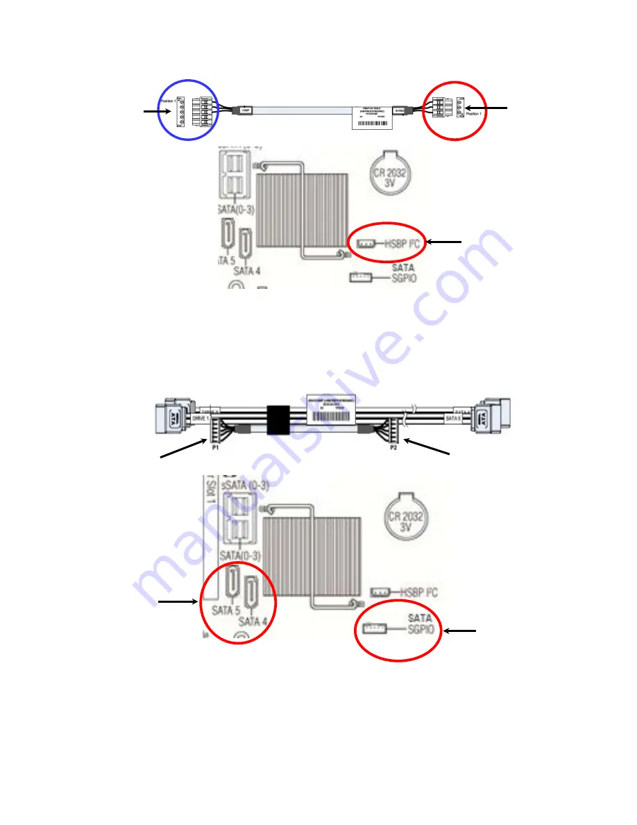
From the backplane accessory kit, locate the I2C cable 

Figure 80. Rear HSBP I2C Cable – iPN H41333 


  Connect the 5-pin I2C cable connector to the matching “HSBP_ I2C” connector on the backplane 


  Connect the 3-pin I2C cable connector to the matching “HSBP_I2C” connector on the server board 


  From the backplane accessory kit, locate the Rear HSBP SGPIO & SATA Cable Bundle 

Figure 81. Rear HSBP SATA & SGPIO Cable Bundle – iPN H41068 


  Match and connect the7-pin SATA “Drive 0” and “Drive 1” cable connectors to the “Drive_0” and 

“Drive_1” connectors on the backplane 


  Connect the 5-pin SATA SGPIO cable connector to the “SGPIO” connector on the backplane 


  Match and connect the7-pin “SATA 4” and “SATA 5” cable connectors to the “SATA_4” and “SATA_5” 

connectors on the server board 


  Connect the 5-pin SATA SGPIO cable connector to the “SGPIO” connector on the server board 

3-pin HSBP I2C to 

Rear  Backplane 

3-pin I2C to 
Server Board 

5-pin I2C to 

Rear Backplane 

5-pin SATA SGPIO to 

rear Backplane 

7-pin SATA ports to 

rear backplane 

7-pin SATA to 

Server Board 

5-pin SATA SGPIO to 

Server Board 

7-pin SATA to 

rear backplane 

5-pin SATA SGPIO 

to rear backplane 

Summary of Contents for R2000WT

Page 1: ...r System R2000WT Product Family System Integration and Service Guide A Guide for Technically Qualified Assemblers of Intel identified Subassemblies Products Rev 1 6 September 2017 Intel Server Boards...

Page 2: ...nged server board mounting screw torque from 8 in lbs to 12 in lbs May 2016 1 3 Added Figure 86 No Front Drive Bay Configuration Chassis only building block Intel Server Chassis R2000WTXXX October 201...

Page 3: ...any intellectual property rights is granted by this document The products described may contain design defects or errors known as errata which may cause the product to deviate from published specific...

Page 4: ...eh usen auf der http www intel com support motherboards server sb cs 010770 htm Consignes de s curit Lisez attention toutes les consignes de s curit et les mises en garde indiqu es dans ce document av...

Page 5: ...jury or equipment damage can result Electrostatic discharge ESD and ESD protection ESD can damage disk drives boards and other parts We recommend that you perform all procedures in this chapter only a...

Page 6: ...ajor components are pre installed in the system Chapter 2 Essential System Component Integration and Service provides instructions for adding essential system components required to complete the integ...

Page 7: ...Family Configuration Guide rev 2 x Intel Server Configurator tool http serverconfigurator intel com For system power budget guidance Intel Server Board S2600WTR Product Family Power Budget Tool and Th...

Page 8: ...1 System Fan Assembly Removal 27 2 4 2 System Fan Assembly Installation 27 2 5 Processor CPU Installation Removal 29 2 5 1 Processor Heatsink s Removal 29 2 5 2 Processor Installation 30 2 5 3 Proces...

Page 9: ...Platform Module TPM Installation 56 3 9 Front Bezel Installation Removal 57 3 9 1 Bezel Snap ons 57 3 9 2 Front Bezel Installation 58 3 9 3 Front Bezel Removal 58 3 10 Intel RAID Maintenance Free Bac...

Page 10: ...d system fan 91 7 2 2 To install a new system fan 91 7 3 Replacing the Standard Front Control Panel R2308WTxxx 92 7 3 1 Standard Front Control Panel Removal R2308WTxxx 92 7 3 2 Standard Front Control...

Page 11: ...ernal Cable Connections 16 Figure 16 R2000WTxxx Front Control Panel and Front I O Internal Cable Connections 17 Figure 17 Hot Swap Backplane Connectors 18 Figure 18 Hot Swap Backplane Power Cable Inst...

Page 12: ...50 Internal fixed mount SSD Installation 41 Figure 51 Removing an internal fixed mount SSD 41 Figure 52 Riser Card Bracket Assemblies 42 Figure 53 PCI Riser Assembly Removal 42 Figure 54 Riser Card In...

Page 13: ...Bay Configuration Chassis only building block Intel Server Chassis R2000WTXXX 80 Figure 87 8 x 3 5 Drive Bay Configuration R2308WT 80 Figure 88 12 x 3 5 Drive Bay Configuration R2312WT Storage System...

Page 14: ...ervice Guide xiv Figure 107 Intel Server System R2224WTxxxx Cable Routing Diagram 106 Figure 108 Intel Server System R2308WTxxxx Cable Routing Diagram 107 Figure 109 Intel Server System R2312WTxxxx Ca...

Page 15: ...oftware vii Table 3 BIOS Setup Keyboard Command Bar 72 Table 4 System Status LED State Definitions 109 Table 5 POST Progress Code LED Example 111 Table 6 MRC Progress Codes 112 Table 7 MRC Fatal Error...

Page 16: ...Intel Server System R2000WT Product Family System Integration and Service Guide xvi Blank Page...

Page 17: ...locks defined above the following system components NOT included will also be needed to complete the full system integration Appropriate SAS SATA Data Cables Appropriate Riser Card s Appropriate Power...

Page 18: ...der can then follow the step by step instructions that will accompany each procedure System Integration Advisory Note It is highly recommended that the system integration process defined in the follow...

Page 19: ...hassis for Assembly As received the Intel Server Chassis will include several components within a boxed accessory kit or placed within the chassis Remove the System Cover Note A non skid surface or a...

Page 20: ...population and safety instructions state that thumbscrews should be tightened with a tool after both initial installation and subsequent access to the panel Chassis Component Identification Figure 3 C...

Page 21: ...Intel Server System R2000WT Product Family System Integration and Service Guide 5 A box with two processor heat sinks Two riser card brackets The system fan assemby...

Page 22: ...receivers on the chassis side wall Grasp each end of the fan assembly and pull straight up until the assembly is fully disengaged from the assembly receivers on the chassis side wall Carefully place...

Page 23: ...static bag Holding the server board by its edges carefully lower the server board into the chassis so that the rear I O connectors of the server board align with and are fully seated into the matching...

Page 24: ...r Duct Side Wall Installation Figure 6 Air Duct Side Wall Installation Locate the two black plastic air duct sidewalls Following the illustration above fasten down the appropriate air duct side wall o...

Page 25: ...Bracket Removal To extract the drive bay retention bracket remove the 6 fastener screws from the top front edge of the drive bay and pull out the metal bracket Set aside the retention bracket and scre...

Page 26: ...y module if applicable Carefully place the chassis on its side and secure each installed drive bay module with one additional screw on the bottom of the chassis see letter F 8 in lbs torque for each s...

Page 27: ...n bracket remove the 6 fastener screws from the top front edge of the drive bay See Letter A and pull out the metal bracket see letter B Remove the 2 fastener screws from the back edge of the drive ba...

Page 28: ...nt Control Panel fastener screw located on the top right side of the I O module bay see letter A Carefully extract the Front Control Panel assembly by pulling it out from the back of the I O Module Ba...

Page 29: ...ositioned when the buttons are protruding from the Control Panel face plate on the front of the drive bay module and the screw holes on the top of the assembly are aligned Using a single screw secure...

Page 30: ...letter A Push the drive bay module in far enough so that the screw holes on the top of the drive bay are properly aligned Using 8 fastener screws secure the drive bay module to the chassis 8 in lbs t...

Page 31: ...sidewalls as shown in the following illustration When routing cables front to back none should be routed through the center of the system or in the area between the system fans and the DIMM slots Cab...

Page 32: ...chassis requiring that they only be connected to the server board when installed Figure 15 R2312WTxxx Front Control Panel and Front I O Internal Cable Connections Locate the Gray 10 pin flat ribbon ca...

Page 33: ...o Figure 16 R2000WTxxx Front Control Panel and Front I O Internal Cable Connections Route the Black round USB cable to the Blue 20 pin connector on the server board labeled Front Panel USB 2 0 3 0 The...

Page 34: ...rs Locate the backplane power cable Figure 18 Hot Swap Backplane Power Cable Installation Connect the 2x4 pin cable connector labeled SVRBRD to the matching 2x4 White power connector on the server boa...

Page 35: ...ce the cable is attached on both ends carefully press the cable as low as possible into the cable routing channel Locate the backplane I2C cable Figure 19 Hot Swap Backplane I2 C Cable Attach the 1x5...

Page 36: ...cable connections will vary depending on the system configuration This section will only describe cable connections when using the onboard SATA controllers For other add in storage options refer to t...

Page 37: ...on board Mini SAS HD connectors for embedded SATA support see illustration 1 3 4 Power Supply Installation Figure 23 Power Supply and Power Supply Bay Filler Installation Insert the power supply modu...

Page 38: ...ty and ESD precautions found in the Warnings section at the beginning of this manual Tools and Supplies Needed Anti static wrist strap and conductive foam pad recommended Phillips cross head screwdriv...

Page 39: ...ck All cables should be routed using the cable channels in between the chassis sidewalls and the air duct side walls as shown in the following illustration When routing cables front to back none shoul...

Page 40: ...nd unplug all peripheral devices and the power cable s Note A non skid surface or a stop behind the server system may be needed to prevent the server system from sliding on your work surface Note Inte...

Page 41: ...less top cover Note Equipment is serviced and maintained only by service persons technically qualified persons The System is not intended to be installed and used in a home school or public area acce...

Page 42: ...he front edge of the air duct with the matching slots on the fan assembly Lower the air duct into the system ensuring the three tabs are securely installed in the fan assembly Press down on the back e...

Page 43: ...until each latch is fully disengaged from the latch receivers on the chassis side wall see letter A Grasp each end of the fan assembly and pull straight up see letter B Carefully place the fan assembl...

Page 44: ...assembly are fully rotated up Position the fan assembly over the chassis so that the latches are oriented toward the front of the chassis see letter A Align the two guide pins on each side of the fan...

Page 45: ...ink Removal Shown with NO processor installed The heatsink is attached to the server board processor socket with captive fasteners Using a 2 Phillips screwdriver loosen the four screws located on the...

Page 46: ...handling the processor 2 Avoid moving around unnecessarily Note The following illustrations to not show the black mylar spacer attached to the processor socket cover This was done for illustration cl...

Page 47: ...or socket Figure 32 Processor Installation Install the Processor Remove processor from its packaging If present carefully remove the protective cover from the bottom side of the processor taking care...

Page 48: ...he Load Plate Figure 35 Processor Installation Latch the Locking Lever Push down on the locking lever on the CLOSE 1st side see letter A Slide the tip of the lever under the notch in the load plate se...

Page 49: ...with screw 1 and engage screw threads by giving it two rotations and stop see letter C Do not fully tighten Proceed to screw 2 and engage screw threads by giving it two rotations and stop see letter...

Page 50: ...system configurations require that specific memory slots be populated at all times using either a DIMM or supplied DIMM Blank Figure 37 DIMM Blank R2312WTxxxx and R2224WTxxxx Storage Models 3 5 x12 an...

Page 51: ...e 35 2 6 3 Removing Memory Figure 39 DDR4 DIMM Removal Locate the DIMM sockets Unlatch the retaining clips located on each end of the socket The DIMM lifts from the socket see letter A Holding the DIM...

Page 52: ...ive bays must be populated with a drive carrier Each drive carrier must have a hard disk drive HDD Solid State Device SSD or a supplied drive blank installed 2 7 1 8 x 3 5 and 12 x 3 5 Front Drive Bay...

Page 53: ...he 3 5 drive blank as a 2 5 device bracket is intended to support SSD type storage devices only Installing a 2 5 hard disk drive into the 3 5 drive blank cannot be supported Figure 43 Option to instal...

Page 54: ...er open insert the drive assembly into the drive bay see letter E Push in the lever to lock it into place see letter F 2 7 2 8 x 2 5 16 x 2 5 and 24 x 2 5 Front Drive Bay Storage 2 7 2 1 2 5 Drive Car...

Page 55: ...ier Verify the connector end of the drive is located towards the back of the carrier see letter E Secure the drive to the carrier using four screws 2 7 2 3 2 5 Drive Carrier Insertion Figure 48 2 5 St...

Page 56: ...ccessory kit locate the peripheral device power cable Figure 49 Peripheral Device Power Cable Connect the 2x3 cable connector labeled SB to the server board Peripheral PWR connector Locate the SATA ca...

Page 57: ...internal SSD is NOT hot swappable Before removing or replacing the drive you must first take the server out of service turn off all peripheral devices connected to the system turn off the system by pr...

Page 58: ...rd Bracket Assemblies This section will provide instructions for the removal and installation of the riser card assemblies from to the system mounting a riser card option to the bracket and installati...

Page 59: ...s fit into the matching key holes on the riser card see letter A Slide the riser card in the direction shown locking the riser card to the bracket see letter B Install the fastener screw to secure the...

Page 60: ...s on the back edge of the riser assembly with the slots on the back of the chassis Once aligned press the riser assembly straight down into the riser slot see letter C NOTE Do NOT rock the riser assem...

Page 61: ...es Intel recommends carrying the system using two people or to use a cart when moving the system from one location to another CAUTION Slide rail mounted equipment is not to be use as a shelf or a work...

Page 62: ...the Warnings section at the beginning of this manual Tools and Supplies Needed 1 Anti static wrist strap and conductive foam pad recommended 2 Phillips cross head screwdriver 1 and 2 bits System Refer...

Page 63: ...stem by pressing the power button and unplug the power cord from the system or wall outlet Figure 58 Installing the Plastic Mounting Clip to an Optical Drive From the system s accessory kit locate the...

Page 64: ...to front should be routed using the cable channels along each chassis sidewall No cables should be routed through the center of the system If installed remove the optical drive bay filler plate from t...

Page 65: ...tem or wall outlet To maintain proper system cooling a filler panel must be installed if you do not install a device at this location Figure 62 Removing the Slimline Optical Drive Remove the system co...

Page 66: ...ower Supply Module Removal Caution The power supply is only hot swappable system does not have to be powered down if the system is configured with two power supply modules operating in a 1 1 Redundant...

Page 67: ...on the back of the power supply module see letter A While pushing up the locking tab on the bottom of the slider adjust the slider to the desired position see letter B Install the power cord into the...

Page 68: ...connector is fully engaged with the matching connector on the server board and the module is firmly seated over each barrel standoff Insert a locking pin into each barrel standoff and connect cables...

Page 69: ...hould be taken NOT to damage the I O shield material when placing the I O module into the back panel cut out Carefully press down on the module to engage the connectors see letter C Secure the module...

Page 70: ...Locate the white 4 pin key connector behind the onboard NIC 2 port on the back edge of the server board To install the key place it over the connector and confirm the orientation of the key matches th...

Page 71: ...Locate the Intel RMM4 Lite connector on the server board near the back of the server board next to the I O Module connector Place the Intel RMM4 Lite key over the connector and match the orientation o...

Page 72: ...TPM Installation Locate the TPM module connector on the server board near the Riser Slot 1 Insert the plastic stand off into the server board mounting hole see letter A Place the TPM module over the c...

Page 73: ...l Snap ons The bezel kit provides three different bezel Snap ons to allow for OEM differentiation two different size badging Snap ons and one decorative wave Snap on Figure 72 Installing the Snap on t...

Page 74: ...side of the bezel towards the chassis Press the left side of the bezel into the rack handle until it clicks into place see letter B Lock the bezel 3 9 3 Front Bezel Removal Figure 75 Removing the Fron...

Page 75: ...MFBU Mounting Bracket Installation Figure 76 Intel RMFBU Installation Locate the RMFBU mounting bracket from the system accessory kit Place the RMFBU bracket onto the air duct see letter A Secure the...

Page 76: ...ing the bay cover plate to the chassis see letter A Unlatch and remove the bay cover plate from the chassis see letter B Carefully remove the backplane module from its packaging Position the drive bay...

Page 77: ...al device power cable Figure 79 Rear HSBP Power Cable iPN G99319 Connect the 2x3 cable connector labeled SB to the server board Peripheral PWR connector Connect the 2x3 cable connector labeled BP to t...

Page 78: ...Match and connect the7 pin SATA Drive 0 and Drive 1 cable connectors to the Drive_0 and Drive_1 connectors on the backplane Connect the 5 pin SATA SGPIO cable connector to the SGPIO connector on the b...

Page 79: ...Raid Expander Mezzanine Card option is mounted internally behind the front drive bays Intel product codes RES2CV360 6Gb and RES3TV360 12Gb Note In order to attach the 6Gb RES2CV360 RAID Expander Card...

Page 80: ...in power connector from the splitter to the middle hot swap backplane 3 12 2 3 5 Front Drive Bay Support For the Intel Server System R2308WTxxxx and R2312WTxxxx an Intel Raid Expander PCIe add in card...

Page 81: ...card Care should be taken when connecting cables from the RAID expander card to the connectors on the backplane because each connector is pre programmed at the factory to provide specific drive ID map...

Page 82: ...5 server system and R2216WT server system can be upgraded to a 24 x 2 5 drive system with the addition of several different 8 x 2 5 Front Drive Bay Module accessory kits available In order to upgrade...

Page 83: ...d pull out the metal bracket see letter B Remove fastener screws over the 1st left most drive bay module and I O Bay Module see letter C Carefully place the chassis on its side From the bottom of the...

Page 84: ...to the chassis using three fastener screws each 8 in lbs torque for each screw Note that the ribbon cables should fit inside cutouts in the chassis sidewall Attach the Left USB flat cable to the Blac...

Page 85: ...for each screw Carefully return the chassis to its original position Install drive bay retention bracket Locate the drive bay retention bracket and screws Carefully slide the drive bay retention brac...

Page 86: ...Intel Server System R2000WT Product Family System Integration and Service Guide 70 Install Intel RAID Expander Card into the chassis See section 3 12...

Page 87: ...ed above The System Update Package will include full system update instructions 4 2 Using the BIOS Setup Utility This section describes how to access and navigate the embedded F2 BIOS Setup utility Th...

Page 88: ...lects the currently highlighted item undoes the pick list and returns the focus to the parent menu Esc Exit The Esc key provides a mechanism for backing out of any field When the Esc key is pressed wh...

Page 89: ...us key on the other keyboards but will have the same effect F9 Setup Defaults Pressing the F9 key causes the following to display Load Optimized Defaults Yes No If Yes is highlighted and Enter is pres...

Page 90: ...on all inner packaging components MUST be reinstalled in the proper location to ensure adequate protection of the system for subsequent shipment NOTE The design of the inner packaging components does...

Page 91: ...am Place 4 foam inserts into the inner box as shown Place the Accessory Kit box between the end foam insert and the bottom foam insert as shown Carefully place the system into the shipping bag Tape th...

Page 92: ...1 foam insert on each side of the system as shown Ensure the bottom tabs of the 2 side foam inserts fit into the end slots of the bottom foam inserts At the back of the system place the corrugated ca...

Page 93: ...essory box and the system front panel place the corrugated cardboard insert iPN H49478 001 Place 2 remaining foam inserts on top of the system in the positions shown Fold the top flaps of the inner bo...

Page 94: ...00WT Product Family System Integration and Service Guide 78 Fold the top flaps of the outer box End flaps first followed by the side flaps Tape the outer box using an H pattern Across the center first...

Page 95: ...or this product family can be obtained from the following Intel documents which can be downloade from the following Intel web site http www intel com support Intel Server System R2000WT Technical Prod...

Page 96: ...ont Drive Bay Configuration Chassis only building block Intel Server Chassis R2000WTXXX Figure 88 8 x 3 5 Drive Bay Configuration R2308WT Figure 89 12 x 3 5 Drive Bay Configuration R2312WT Storage Sys...

Page 97: ...mily System Integration and Service Guide 81 Figure 92 24 x 2 5 Drive Bay Configuration R2224WT Storage System 6 1 2 Control Panel Features Figure 93 Control Panel Features Video USB 2 0 3 0 SATA Slim...

Page 98: ...tem Integration and Service Guide 82 6 1 3 Front I O Features Non Storage Systems Figure 94 Front I O Panel Features 6 1 4 Back Panel Features Figure 95 Back Panel Features 6 1 5 Server Board Features...

Page 99: ...Intel Server System R2000WT Product Family System Integration and Service Guide 83 Figure 97 Intel Light Guided Diagnostic LEDs Server Board...

Page 100: ...Intel Server System R2000WT Product Family System Integration and Service Guide 84 Figure 98 DIMM Fault LEDs...

Page 101: ...BIOS Defaults 3 Wait 5 seconds then move the jumper back to pins 1 2 4 Re install the system top cover 5 Re Install system power cords Note The system will automatically power on after AC is applied...

Page 102: ...the Password Clear jumper back to pins 1 2 default 9 Re install the system top cover and reattach the AC power cords 10 Power up the server 11 Strongly recommended Boot into F2 BIOS Setup immediately...

Page 103: ...ng the update files 9 Update the BMC firmware using the following command FWPIAUPD u bin ni b o pia if usb file name BIN 10 When the update has successfully completed power off the system 11 Remove th...

Page 104: ...em top cover and re attach the AC power cords 6 Power on the system 7 The system will automatically boot to the EFI shell Update the BIOS using the standard BIOS update instructions provided with the...

Page 105: ...s 2 and 3 These include Processors Memory Riser Cards Add in cards I O Modules Storage Devices Power Supplies SATA Optical Drive Before You Begin Before working with your server product observe the sa...

Page 106: ...verand ren Advarsel Lithiumbatteri Eksplosjonsfare Ved utskifting benyttes kun batteri som anbefalt av apparatfabrikanten Brukt batteri returneres apparatleverand ren Varning Explosionsfara vid felakt...

Page 107: ...two loop handles on the top side of the fan and pull straight up until it clears the fan assembly bracket Figure 101 System Fan Installation 7 2 2 To install a new system fan Locate the replacement f...

Page 108: ...e hotswap backplane disconnect the 2x2 pin backplane power cable all cables connected to the mini SAS HD connectors and the 5 pin I2C cable Identify and remove the bottom four storage drives from the...

Page 109: ...ttons is securely in place before installing the control panel board into the drive bay module The control panel is properly positioned when the buttons are protruding from the Control Panel face plat...

Page 110: ...ndard Front Control Panel R2208WTxxx R2216WTxxx 7 4 1 Standard Front Control Panel Removal R2208WTxxx R2216WTxxx Power off the system and remove all power cords Remove the system top cover see section...

Page 111: ...ve the fastener screw from the bottom of the I O Bay module see letter D Carefully return the server to its original position Carefully remove the I O Bay module from the chassis Remove fastener screw...

Page 112: ...ote Ensure the plastic gasket over the control panel buttons is securely in place before installing the control panel board into the drive bay module The control panel is properly positioned when the...

Page 113: ...assis using six fastener screws 8 in lbs torque see letter B Secure the I O Module bay to the chassis using two fastener screws 8 in lbs torque see letter C Carefully place the system on its side and...

Page 114: ...ached to add in PCIe add cards and I O modules Remove riser card assemblies see section 2 8 1 Remove all options installed onto the server board including if installed Intel I O Module Intel SAS RAID...

Page 115: ...from its anti static bag Carefully lower the server board into the chassis so that the rear I O connectors of the server board align with and are fully seated into the matching holes on the chassis ba...

Page 116: ...reviously removed from the server board Install processor s see section 2 5 2 Install DIMMs see section 2 6 2 Re Install all options previously removed from the server board Re Install riser card asse...

Page 117: ...Intel Server System R2000WT Product Family System Integration and Service Guide 101 Blank Page...

Page 118: ...ver and chassis accessory parts list for ordering upgrades or spare parts A searchable knowledgebase to search for product information throughout the support site 2 If you are still unable to obtain a...

Page 119: ...ting cables from front to back All cables should be routed using the cable channels in between the chassis sidewalls and the air duct side walls as shown in the following illustration When routing cab...

Page 120: ...Intel Server System R2000WT Product Family System Integration and Service Guide 104 Figure 106 Intel Server System R2208WTxxxx Cable Routing Diagram...

Page 121: ...Intel Server System R2000WT Product Family System Integration and Service Guide 105 Figure 107 Intel Server System R2216WTxxxx Cable Routing Diagram...

Page 122: ...Intel Server System R2000WT Product Family System Integration and Service Guide 106 Figure 108 Intel Server System R2224WTxxxx Cable Routing Diagram...

Page 123: ...Intel Server System R2000WT Product Family System Integration and Service Guide 107 Figure 109 Intel Server System R2308WTxxxx Cable Routing Diagram...

Page 124: ...Intel Server System R2000WT Product Family System Integration and Service Guide 108 Figure 110 Intel Server System R2312WTxxxx Cable Routing Diagram...

Page 125: ...is not exhibiting any errors AC power is present and BMC has booted and manageability functionality is up and running After a BMC reset and in conjuction with the Chassis ID solid ON the BMC is bootin...

Page 126: ...Unit Redundancy sensor Insufficient resources offset indicates not enough power supplies present In non sparing and non mirroring mode if the threshold of correctable errors is crossed within the wind...

Page 127: ...isolate the possible cause of the hang condition Each POST code is represented by eight LEDs four Green and four Amber The POST codes are divided into two nibbles an upper nibble and a lower nibble Th...

Page 128: ...ank information B5h 1 0 1 1 0 1 0 1 Program registers on the channel level B6h 1 0 1 1 0 1 1 0 Perform the JEDEC defined initialization sequence B7h 1 0 1 1 0 1 1 1 Train DDR3 ranks B8h 1 0 1 1 1 0 0...

Page 129: ...1 1 0 1 0 1 0 DDR3 channel training error 01h Error on read DQ DQS Data Data Strobe init 02h Error on Receive Enable 3h Error on Write Leveling 04h Error on write DQ DQS Data Data Strobe EBh 1 1 1 0 1...

Page 130: ...1 0 0 1 End Of Sec Phase 0Eh 0 0 0 0 1 1 1 0 Microcode Not Found 0Fh 0 0 0 0 1 1 1 1 Microcode Not Loaded PEI Phase 10h 0 0 0 1 0 0 0 0 PEI Core 11h 0 0 0 1 0 0 0 1 CPU PEIM 15h 0 0 0 1 0 1 0 1 NB PE...

Page 131: ...USB detect 9Dh 1 0 0 1 1 1 0 1 DXE USB enable A1h 1 0 1 0 0 0 0 1 DXE IDE begin A2h 1 0 1 0 0 0 1 0 DXE IDE reset A3h 1 0 1 0 0 0 1 1 DXE IDE detect A4h 1 0 1 0 0 1 0 0 DXE IDE enable A5h 1 0 1 0 0 1...

Page 132: ...1 1 0 0 0 0 1 S3 Resume PEIM S3 boot script E2h 1 1 1 0 0 0 1 0 S3 Resume PEIM S3 Video Repost E3h 1 1 1 0 0 0 1 1 S3 Resume PEIM S3 OS wake BIOS Recovery F0h 1 1 1 1 0 0 0 0 PEIM which detected force...

Page 133: ...ting in the BIOS setup determines whether the system pauses to the Error Manager for this type of error so the user can take immediate corrective action or the system continues booting Note that for 0...

Page 134: ...update mode Major 84F4 Sensor data record empty Major 84FF System event log full Minor 8500 Memory component could not be configured in the selected RAS mode Major 8501 DIMM Population Error Major 852...

Page 135: ...2 DIMM_A3 disabled Major 8543 DIMM_B1 disabled Major 8544 DIMM_B2 disabled Major 8545 DIMM_B3 disabled Major 8546 DIMM_C1 disabled Major 8547 DIMM_C2 disabled Major 8548 DIMM_C3 disabled Major 8549 DI...

Page 136: ...2 DIMM_G1 encountered a Serial Presence Detection SPD failure Major 8573 DIMM_G2 encountered a Serial Presence Detection SPD failure Major 8574 DIMM_G3 encountered a Serial Presence Detection SPD fail...

Page 137: ...sence Detection SPD failure Major 85E6 DIMM_N3 encountered a Serial Presence Detection SPD failure Major 85E7 DIMM_P1 encountered a Serial Presence Detection SPD failure Major 85E8 DIMM_P2 encountered...

Page 138: ...during runtime 1 long Intel TXT security violation 0xAE 0xAF System halted because Intel Trusted Execution Technology detected a potential violation of system security 3 Memory error Multiple System...

Page 139: ...t has incompatible power capabilities 1 5 4 2 Power fault DC power unexpectedly lost power good dropout Power unit sensors report power unit failure offset 1 5 4 4 Power control fault power good asser...

Page 140: ...__________________________________________________ _____________________________________________________________________________________________ _______________________________________________________...

Reviews: