Intel® Server System R2000WF Product Family Technical Product Specification
75
LEDs to indicate drive activity and status for each attached device
Device presence detect inputs to the microcontroller
5 V VR for devices
3.3 V VR for microcontroller
In-application microcontroller firmware updateable over the I2C interface
FRU EEPROM support
Temperature sensor through the use of a TMP75 (or equivalent) thermistor implementation with the
microcontroller
6.4.1
SGPIO Functionality
Backplanes include support for a SFF-8485 compliant SGPIO interface used to activate the status LED. This
interface is also monitored by the microcontroller for generating FAULT, IDENTIFY, and REBUILD registers
that in turn are monitored by the server board BMC for generating corresponding SEL events.
6.4.2
I2C Functionality
The microcontroller has a master/slave I2C connection to the server board BMC. The microcontroller is not
an IPMB compliant device. The BMC generates SEL events by monitoring registers on the HSBP
microcontroller for DRIVE PRESENCE, FAULT, and RAID REBUILD in progress.
6.5
8 x 2.5” Drive SATA/SAS/NVMe* Combo Backplane
This section applies to the 8 x 2.5” drive SAS/SATA/NVMe combo backplane (iPC – F2U8X25S3PHS).
All system SKUs capable of supporting 2.5” drives will include one or more eight drive backplanes capable of
supporting 12 Gb/sec SAS, 6 Gb/sec SATA drives, and PCIe NVMe* drives.
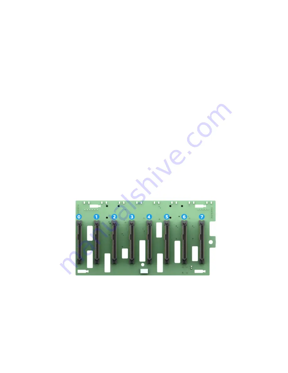
The front side of the backplane includes 68-pin SFF-8639 drive interface connectors, each capable of
supporting SAS, SATA, or NVMe drives. The connectors are numbered 0 through 7.
Figure 50. 8 x 2.5" SAS/SATA/NVMe* hot swap backplane, front side
The backside of the backplane includes two multi-port mini-SAS HD connectors labeled SAS/SATA_0-3 and
SAS/SATA_4-7, and eight PCIe OCuLink connectors, each labeled PCIe SSD#, where # = 0 -7, one connector
for each installed NVMe drive.
Summary of Contents for R2000WF series
Page 2: ...Blank page...


