background image

AF003684

Screw

A

B

C

AF003686

D


42

Intel

® 

Server System R1304BTSSFAN/R1304BTLSFAN/R1304BTLSHBN Service Guide

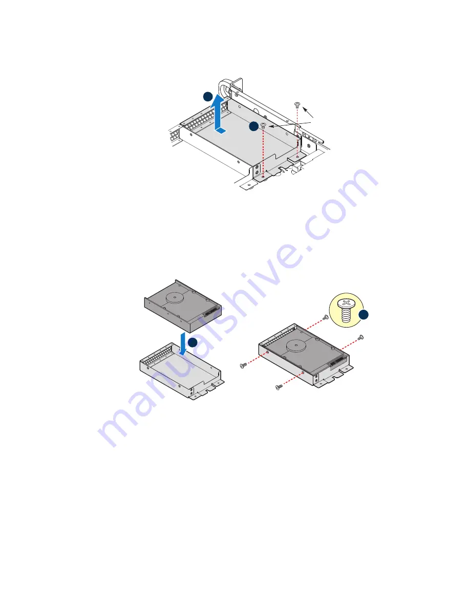
Figure 22. Removing Drive Carrier from the Server System (R1304BTLSFAN)

7. Insert hard drive into the carrier with the bottom-side of the drive facing up.
8. Attach the hard drive to the carrier with four screws as shown.
9. Re-install the hard drive/carrier assembly into the chassis.

Figure 23. Installing Drive into Drive Carrier (R1304BTSSFAN/

R1304BTLSFAN)

10. Secure the hard drive/carrier assembly with the screws.
11. Connect the data cables to the drive(s).
12. Connect the power cables to the drive(s).
13. Install the server system cover. For instructions, see 

“Installing the Server System 

Cover” on page 29

Summary of Contents for R1304BTLSFAN

Page 1: ...Intel Server System R1304BTSSFAN R1304BTLSFAN R1304BTLSHBN Service Guide A Guide for Technically Qualified Assemblers of Intel Identified Subassemblies Products Intel Order Number G21355 003...

Page 2: ...death may occur Intel may make changes to specifications and product descriptions at any time without notice Intel server boards contain a number of high density VLSI and power delivery components tha...

Page 3: ...d Servergeh usen auf der Intel Server Deployment Toolkit CD oder unter http www intel com support motherboards server sb cs 010770 htm Consignes de s curit Lisez attention toutes les consignes de s cu...

Page 4: ...iv Intel Server System R1304BTSSFAN R1304BTLSFAN R1304BTLSHBN Service Guide...

Page 5: ...or equipment damage can result Electrostatic discharge ESD and ESD protection ESD can damage disk drives boards and other parts We recommend that you perform all procedures in this chapter only at an...

Page 6: ...vi Intel Server System R1304BTSSFAN R1304BTLSFAN R1304BTLSHBN Service Guide...

Page 7: ...product diagrams to help you identify components and their locations Chapter 2 provides instructions on using the utilities shipped with the board or that may be required to update the system This in...

Page 8: ...heat sink in the server system product box Four hard disk drive brackets installed in the server system One PCI E X 8 low profile riser card with supporting bracket installed in the server system Rack...

Page 9: ...handles installed in the server system Standard front panel installed in the server system Cables Four SATA cables for SATA HDDs One front panel USB cable installed in the server system One front pane...

Page 10: ...product box Four hot swap hard disk drive carriers installed in the server system One PCI E x 8 low profile riser card with supporting bracket installed in the server system Rack handles installed in...

Page 11: ...boards adapter cards and operating systems that have been tested with this product For the Tested Hardware Operating Systems List you can go to the Intel Server Configurator Tool http serverconfigura...

Page 12: ...xii Intel Server System R1304BTSSFAN R1304BTLSFAN R1304BTLSHBN Service Guide...

Page 13: ...erver System References xi Chapter 1 Server System Features 1 Chassis Component Identification 4 System Front Panel 4 System Rear 6 Peripheral Devices R1304BTSSFAN R1304BTLSFAN 7 Peripheral Devices R1...

Page 14: ...the Processor 35 Removing the Heat Sink and Processor 35 Installing the Processor 36 Installing the Heat Sink 39 Installing and Removing a Hard Drive R1304BTSSFAN R1304BTLSFAN 41 Installing a Hard Dis...

Page 15: ...g the System 75 Problems following Initial System Installation 76 First Steps Checklist 76 Hardware Diagnostic Testing 77 Verifying Proper Operation of Key System Lights 77 Confirming Loading of the O...

Page 16: ...TSSFAN R1304BTLSFAN R1304BTLSHBN Service Guide LED Information 84 BIOS POST Beep Codes 84 Appendix C Warranty 85 Limited Warranty for Intel Chassis Subassembly Products 85 Appendix D Getting Help 89 W...

Page 17: ...38 Figure 21 Installing the Heat Sink 39 Figure 22 Removing Drive Carrier from the Server System R1304BTLSFAN 42 Figure 23 Installing Drive into Drive Carrier R1304BTSSFAN R1304BTLSFAN 42 Figure 24 Re...

Page 18: ...xviii Intel Server System R1304BTSSFAN R1304BTLSFAN R1304BTLSHBN Service Guide Figure 43 Cable Routing R1304BTLSHBN 72...

Page 19: ...304BTLSHBN Feature Summary 2 Table 2 Control Panel LED Functions 4 Table 3 NIC LED Descriptions 6 Table 4 Memory Configuration Table 16 Table 5 Setup Menu Key Use 20 Table 6 Power Supply Output Capabi...

Page 20: ...xx Intel Server System R1304BTSSFAN R1304BTLSFAN R1304BTLSHBN Service Guide...

Page 21: ...s illustrations of the product a list of the server system features and diagrams showing the location of important components and connections on the server system Figure 1 Intel Server System R1304BTS...

Page 22: ...point to point DMI interface to PCH LGA 1155 pin socket Max TDP 95W Memory Two memory channels with support for 1066 1333 ECC Unbuffered UDIMM Up to 2 UDIMMs per channel 32 GB max with x8 ECC UDIMM 2...

Page 23: ...ves SAS drives are supported when a SAS add on card is installed Peripherals Slimline bay for SATA optical drive optional Front panel Standard front panel Power Supply Intel Server System R1304BTSSFAN...

Page 24: ...s are not used on the Intel Server Systems R1304BTSSFAN R1304BTLSFAN or R1304BTLSHBN Unstuffable ID Button with ID LED and Status Fault LED is not used on Intel Server System R1304BTSSFAN Figure 3 Fro...

Page 25: ...ure Critical temp voltage threshold VDR hot asserted min number fans not present or failed Off AC power off System unplugged AC power on System powered off and in standby no prior degraded non critica...

Page 26: ...Green Off LAN link is not established On LAN link is established Blinking LAN activity is occurring Right N A Off 10 Mbit sec data rate is selected Green On 100 Mbit sec data is selected Yellow On 10...

Page 27: ...AN R1304BTLSFAN on page 41 on Page 41 Note Each drive can consume up to 17 W of power Drives must be specified to run at a maximum ambient temperature of 45 C Note The Intel Server System R1304BTSSFAN...

Page 28: ...rvice Guide Internal Components R1304BTSSFAN Figure 5 System Components R1304BTSSFAN A Rack Handles two F System Memory DIMM Sockets B Server Board G Cooling Fans C PCIe Riser Assembly H Front Panel D...

Page 29: ...ernal Components R1304BTLSFAN Figure 6 System Components R1304BTLSFAN A Rack Handles two F System Memory DIMM Sockets B Server Board G Cooling Fans C PCIe Riser Assembly H Front Panel D Processor and...

Page 30: ...Internal Components R1304BTLSHBN Figure 7 System Components R1304BTLSHBN A Rack Handles two F System Memory DIMM Slots B Server Board G Cooling Fans C PCIe Riser Assembly H Front Panel Board D Proces...

Page 31: ...B Slot 5 6 PCI Express Gen2 x4 x8 connector O CPU connector C SATA_KEY P CPU Fan connector D Slot 7 PCI Express Gen2 x8 x16 connector Q Chassis Intrusion E Ethernet and Dual USB COMBO R SATA_SGPIO F E...

Page 32: ...gure 8 Intel Server Board S1200BTS Layout Server Board Connectors Components S1200BTL J SYS_FAN_2 W CMOS battery K DIMM slots X Front Panel L MAIN power connector Y HDD LED M TPM connector A Slot 1 32...

Page 33: ...n2 x8 x16 connector V SAS Module connector F Chassis Intrusion W IPMB G SATA_KEY X SYS_FAN_1 H Two Ethernet and Dual USB COMBO Y HSBP I Video port Z SATA_SGPIO J External Serial port AA Internal Seria...

Page 34: ...ted RTC 3 2 Default J1G1 Password Clear Cleared 3 2 Default J2J1 Enabled ME Force Update 14 Intel Server System R1304BTSSFAN R1304BTLSFAN R1304BTLSHBN Service Guide Configuration Jumpers Figure 10 Con...

Page 35: ...itiates a clearing of password Protected RTC CMOS clear Jumper in normal position pins 1 2 allows the system to successfully POST and boot to the operating system environment BIOS settings are kept in...

Page 36: ...oin For a complete list of supported memory DIMMs see the links under Server System References on page xi Table 4 Memory Configuration Table A1 only Single Channel B1 only Single Channel A1 Single Cha...

Page 37: ...default Maximum Performance Mode preferred for Intel Xeon E3 1200 based platforms All three channels may be populated in any order and have no matching requirements All channels must run at the same...

Page 38: ...18 Intel Server System R1304BTSSFAN R1304BTLSFAN R1304BTLSHBN Service Guide...

Page 39: ...ditions listed previously during the Power On Self Test POST you will see this prompt Press F2 to enter SETUP In a third condition when CMOS NVRAM is corrupted you will see other prompts but not the F...

Page 40: ...he values in the associated pick list without displaying the full list On 106 key Japanese keyboards the plus key has a different scan code than the plus key on the other keyboard but it has the same...

Page 41: ...follow a recovery process to return the system to service See Server System References on page xi for a link to necessary software and instructions Recording the Current BIOS Settings 1 Boot the compu...

Page 42: ...s save your settings and exit Setup Recovering the BIOS If an update to the system BIOS is not successful or if the system fails to complete POST and the BIOS is unable to boot an operating system it...

Page 43: ...into the AC power source and power it up to confirm the recovery was successful 10 Do NOT interrupt the BIOS POST during the first boot Clearing the Password 11 If the user or administrator password s...

Page 44: ...t being in the proper update state the server board provides an Integrated BMC Force Update jumper which forces the Integrated BMC into the proper update state You should complete the following proced...

Page 45: ...ides an Integrated BMC Force Update jumper which forces the ME into the proper update state The following procedure should be completed in the event the standard ME firmware update process fails 1 Pow...

Page 46: ...26 Intel Server System R1304BTSSFAN R1304BTLSFAN R1304BTLSHBN Service Guide...

Page 47: ...uctions Note Most of the illustrations in this chapter show the Intel Server System R1304BTLSFAN with an optional optical drive installed Unless otherwise noted the instructions for removing and insta...

Page 48: ...AC power cable Note You may need a non skid surface or a stop behind the server system to prevent the server system from sliding on your work surface AF003681 C A B B 1 Observe the safety and ESD pre...

Page 49: ...of this book See Safety Information on page iii 2 Place the cover over the server system so that the side edges of the cover sit just inside the server system sidewalls Slide the cover forward See le...

Page 50: ...ired for proper airflow within the server system Removing the Processor Air Duct 1 Observe the safety and ESD precautions at the beginning of this book See Safety Information on page iii 2 Power down...

Page 51: ...nd the AC power cable 3 Remove the server system cover For instructions see Removing the Server System Cover on page 28 4 Lower the air duct into place insert the two hooks at the front of the process...

Page 52: ...off all peripheral devices connected to the system turn off the system by pressing the power button and unplug the AC power cord from the system or wall outlet The silkscreen on the board for the DIM...

Page 53: ...osition See letter A in Figure 15 6 Holding the DIMM by the edges remove it from its anti static package 7 Position the DIMM above the socket Align the notch on the bottom edge of the DIMM with the ke...

Page 54: ...r instructions see Removing the Server System Cover on page 28 4 Locate the DIMM sockets See Figure 15 5 Gently spread the retaining clips at each end of the socket The DIMM lifts from the socket 6 Ho...

Page 55: ...e handling the processor 2 Avoid moving around unnecessarily Removing the Heat Sink and Processor 1 Observe the safety and ESD precautions at the beginning of this book See Safety Information on page...

Page 56: ...the server and unplug all peripheral devices and the AC power cable 3 Remove the server system cover For instructions see Removing the Server System Cover on page 28 4 Locate the processor socket and...

Page 57: ...17 Opening the Load Plate Caution Do not touch the socket pins they are very sensitive and easily damaged 6 Remove the processor from the packaging box and remove the protective shipping cover See Fig...

Page 58: ...9 Installing the Processor Note Make sure the alignment triangle mark and the alignment triangle cutout align correctly 9 Remove the protective socket cover See Figure 20 Figure 20 Removing the Protec...

Page 59: ...touch the TIM 2 Orient the heat sink over the processor as shown in Figure 21 You must position the fins as shown to provide correct airflow through the system 3 Set the heat sink over the processor...

Page 60: ...40 Intel Server System R1304BTSSFAN R1304BTLSFAN R1304BTLSHBN Service Guide 7 Install the server system cover For instructions see Installing the Server System Cover on page 29...

Page 61: ...ort all hard drives See Server System References on page xi for an Internet link to a list of supported hardware Installing a Hard Disk Drive R1304BTSSFAN R1304BTLSFAN Note If you are replacing a hard...

Page 62: ...ing up 8 Attach the hard drive to the carrier with four screws as shown 9 Re install the hard drive carrier assembly into the chassis Figure 23 Installing Drive into Drive Carrier R1304BTSSFAN R1304BT...

Page 63: ...e the drive carrier from the chassis 7 Remove the four screws that attach the hard drive to the drive carrier Lift the drive from the carrier Store the drive in an anti static bag 8 If you are install...

Page 64: ...of supported hardware Installing a Hot Swap SATA Drive R1304BTLSHBN 1 If it is installed remove the front bezel 2 Locate the drive position you want to use 3 Open the latch at the front of the hard dr...

Page 65: ...in Figure 25 Figure 25 Installing Drive into Drive Carrier R1304BTLSHBN 10 With the black lever in the fully open position slide the drive assembly into the server system see letter E in Figure 26 The...

Page 66: ...of the hard drive carrier 3 Pull out on the black lever to slide the carrier from the server system 4 Remove the four screws that attach the hard drive to the drive carrier Lift the drive from the ca...

Page 67: ...system even if no hard drive is installed in it 8 When the black lever begins to close by itself push on it to lock the drive carrier into place 9 Install the server system cover For instructions see...

Page 68: ...ystem or wall outlet Installing a Slimline Optical Drive Notes If you are replacing an optical drive see Installing a Slimline Optical Drive on page 48 for instructions first Return to these steps whe...

Page 69: ...e data cable to the optical drive and to the SATA connector on the server board 9 Slide the optical drive assembly in through the front of the chassis Figure 29 Installing the Optical Drive into the S...

Page 70: ...oving the Server System Cover on page 28 4 Press down the latch and then Slide the optical drive out through the front of the system 5 Disconnect the optical drive power and data cables 6 Remove the s...

Page 71: ...embly To remove the PCIe riser assembly use the following instructions AF003683 Riser Card Connector 1 Observe the safety and ESD precautions at the beginning of this book See Safety Information on pa...

Page 72: ...ssembly into your server system 1 Lower the riser assembly into place over the add in card slot See letter B in Figure 31 2 Align the three hooks in the riser assembly with the matching slots at the b...

Page 73: ...the safety and ESD precautions at the beginning of this book See Safety Information on page iii 2 Power down the server and unplug all peripheral devices and the AC power cable 3 Remove the server sys...

Page 74: ...on page 51 6 Remove any add in cards from the PCIe Riser connector For instructions see Removing a PCI Add in Card on page 56 7 Use two screws to attach the riser card to the riser assembly See Figur...

Page 75: ...able 3 Remove the server system cover For instructions see Removing the Server System Cover on page 28 4 Remove the PCIe Riser assembly For instructions see Removing the PCIe Riser Assembly on page 51...

Page 76: ...e the safety and ESD precautions at the beginning of this book See Safety Information on page iii 2 Power down the server and unplug all peripheral devices and the AC power cable 3 Remove the server s...

Page 77: ...9 Install the PCIe Riser assembly into the server system For instructions see Installing the PCIe Riser Assembly on page 52 10 Install the processor air duct For instructions see Installing the Proce...

Page 78: ...System Cover on page 28 4 Remove the processor air duct For instructions see Removing the Processor Air Duct on page 30 5 Remove the PCIe Riser assembly For instructions see Removing the PCIe Riser A...

Page 79: ...For instructions see Installing the Server System Cover on page 29 17 Plug all peripheral devices and the AC power cable into the server Installing the Server Board 1 Observe the safety and ESD preca...

Page 80: ...or data cable routing information see 11 Connect the power cables For power cable routing information see Cable Routing on page 69 12 Install the PCIe Riser assembly For instructions see Installing th...

Page 81: ...hiumbatteri Eksplosionsfare ved fejlagtig h ndtering Udskiftning m kun ske med batteri af samme fabrikat og type Lev r det brugte batteri tilbage til leverand ren Advarsel Lithiumbatteri Eksplosjonsfa...

Page 82: ...e CMOS Battery 7 Dispose of the battery according to local ordinance 8 Remove the new lithium battery from its package and being careful to observe the correct polarity insert it in the battery socket...

Page 83: ...fety Information on page iii 2 Power down the server and unplug all peripheral devices and the AC power cable 3 Remove the server system cover For instructions see Removing the Server System Cover on...

Page 84: ...lace the power supply If one of the fans fails you can individually replace them If a fan in the power supply fails you must replace the power supply Use the following steps to replace a system fan or...

Page 85: ...n assembly into the system Use caution to make sure you do not pinch any cables 10 Route the cable from the fan at the right around the right side of the assembly and under the clip at the front of th...

Page 86: ...e iii 2 Power down the server and unplug all peripheral devices and the AC power cable 3 If it is installed remove the front bezel if it is installed 4 Attach the rack handle to the server system with...

Page 87: ...iii 2 Power down the server and unplug all peripheral devices and the AC power cable 3 If it is installed remove the front bezel 4 Remove the two screws holding the rack handle in place and remove th...

Page 88: ...68 Intel Server System R1304BTSSFAN R1304BTLSFAN R1304BTLSHBN Service Guide...

Page 89: ...fans is not blocked Use the following figures to determine the correct cable routing For readability separate figures for power cable routing and data cable routing are included Make sure all necessa...

Page 90: ...Cable Routing R1304BTSSFAN Figure 41 Cable Routing R1304BTSSFAN A Internal USB to Front H System FAN2 B Front Panel I System FAN3 C SATA port to HSBP HDD0 J Power Supply to Main Power D SATA port to H...

Page 91: ...de 71 Cable Routing R1304BTLSFAN Figure 42 Cable Routing R1304BTLSFAN A Internal USB to Front I System FAN3 B Front Panel J Power Supply to Main Power C SATA port to HSBP HDD0 K Power Supply to P S AU...

Page 92: ...ice Guide Cable Routing R1304BTLSHBN Figure 43 Cable Routing R1304BTLSHBN A Power Supply to CPU Power I SATA port to HSBP HDD1 B Power Supply to P S AUX J SATA port to HSBP HDD2 C Power Supply to Main...

Page 93: ...e power subsystem for each voltage For information about calculating the power usage for your configuration see Calculating Power Usage Table 6 Power Supply Output Capability 3 3 V 14 A 5 0 V 18 A 5 V...

Page 94: ...ot to exceed 10 C per hour Humidity Non operating 90 relative humidity non condensing at 35 C Shock Operating Packaged 2 0 g 11 msec 1 2 sine Operational after an 24 inch free fall Acoustic noise 7 Be...

Page 95: ...called the Platform Confidence Test that may help with your diagnostics See Server System References on page xi for a link to this software If you cannot resolve your server problems on your own see...

Page 96: ...the server board correct Are all jumper and switch settings on add in boards and peripheral devices correct To check these settings refer to the manufacturer s documentation that comes with them If a...

Page 97: ...video display monitor 4 If the operating system normally loads from the hard disk drive make sure there is no CD ROM DVD disk in the optical drive 5 If the power LED does light attempt to boot from a...

Page 98: ...er cord into the power supply Some ATX power supplies have a power switch on the back of the power supply If your system has one is it turned on Remove all add in cards and see if the system boots If...

Page 99: ...or s and re seat them If you are using an add in video controller board do the following 1 Verify the video works using the onboard video controller 2 Verify the video controller board is fully seated...

Page 100: ...have power connector plugs been forced into power connector sockets the wrong way Drive Activity Light Does Not Light Check the following Are the drive s power and signal cables properly installed Ar...

Page 101: ...ts are not shared See the documentation that came with your PCI card s for information on changing interrupts Diagnostics pass but the connection fails Make sure the network cable is securely attached...

Page 102: ...Make sure the software is properly installed and configured for the system See the software documentation Use only an authorized copy Unauthorized copies often do not work If you are running the softw...

Page 103: ...and chipset files Hard Drive s are not Recognized Check the following Make sure the drive is not disabled in BIOS Setup Make sure the drive is connected correctly and that is plugged into the power su...

Page 104: ...POST Code 1 8 Display boot 80 POST code Left rear of board Each LED can be Off Green Amber or Red See the POST code table 5 V Standby Identify 5 V standby power on state Front left board Amber On 5 V...

Page 105: ...t with another Product OR REFUND the then current value of the Product if Intel is unable to repair or replace the Product If such Product is defective transportation charges for the return of Product...

Page 106: ...es are the sole and exclusive remedies for any breach of warranty Intel is not responsible for direct special incidental or consequential damages resulting from any breach of warranty under another le...

Page 107: ...m In Europe and in Asia Contact your original authorized distributor for warranty service Any replacement Product is warranted under this written warranty and is subject to the same limitations and ex...

Page 108: ...88 Intel Server System R1304BTSSFAN R1304BTLSFAN R1304BTLSHBN Service Guide...

Page 109: ...support at any time without notice Before calling fill out an Intel Server Issue Report Form You can find a sample form at http www intel com support motherboards server For the fastest service pleas...

Page 110: ...Myanmar 63 2 636 9796 via Philippines New Zealand 0800 444 365 Pakistan 632 63684 15 IDD via Philippines Philippines 1 800 1 651 0117 Singapore 65 6213 1311 Taiwan 2 2545 1640 Thailand 1 800 631 0003...

Page 111: ...ial 800 843 4481 Pacifictel Contact AT T USA at 1 800 225 528 Once connected dial 800 843 4481 Guatemala Contact AT T USA at 99 99 190 Once connected dial 800 843 4481 Mexico Contact AT T USA at 001 8...

Page 112: ...92 Intel Server System R1304BTSSFAN R1304BTLSFAN R1304BTLSHBN Service Guide...

Reviews: