Intel
®
Server System R1000WF Product Family System Integration and Service Guide
11
f)
Locate the three (3) support bracket screws, two long and one short.
g)
Using 8 in-lb. torque, secure the Chassis Support Bracket to the server board in the order specified;
outer screws (#3 & #4) first, followed by the center screw (#5). Note that the center screw (#5) is
shorter than the two outer screws.
h)
Go back and securely tighten the air duct side wall screws (#1 and #2 in the illustration) using 8 in-
lbf. torque
i)
Attach the blue 20-pin cable connector of the Front USB Cable (from the previous section) to the
matching blue 20-pin connector on the server board labeled “FP USB 2.0/3.0”. Push the cable down
as far as possible into the cable routing channel.
1.3.1
Power Supply Module Installation
The server system can support 1 or 2 power supply modules.
1.
Install the Power Supply Module(s)
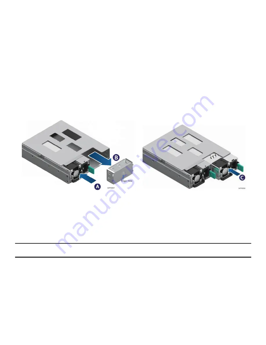
Figure 17. Power Supply and Power Supply Bay Filler Installation
a)
Insert the 1
st
power supply into the left most power supply bay until it clicks and locks into place.
(See letter ‘A)
b)
(Optional) To install a 2
nd
power supply, remove the insert from the 2
nd
chassis power supply bay
(See letter ‘B’)
c)
(Optional) Install the 2
nd
power supply (See letter ‘C’)
Note: A single power supply configuration requires that the power supply bay insert be installed when the
system is operational.
Continue on to Chapters 2 and 3 for installation of processors, memory, add-in cards, storage devices, and
other supported options.


