


Chapter 2 Hardware Configuration
PMB-601LF USER
′
S MANUAL
Page: 2-15
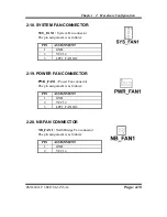
2-18. SYSTEM FAN CONNECTOR
SYS_FAN1 :
System Fan connector
The pin assignment is as follows:
PIN ASSIGNMENT
1 GND
2 VCC12
3 LPC1_FANIO2
2-19. POWER FAN CONNECTOR
PWR_FAN1 :
Power Fan connector
The pin assignment is as follows:
PIN ASSIGNMENT
1 GND
2 VCC12
3 LPC1_FANIO3
2-20. NB FAN CONNECTOR
NB_FAN1 :
North Bridge Fan connector
The pin assignment is as follows:
PIN ASSIGNMENT
1 GND
2 VCC12