


Chapter 2 Hardware Configuration
PMB-601LF USER
′
S MANUAL
Page: 2-11
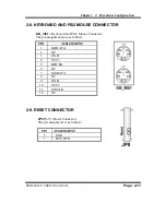
2-8. KEYBOARD AND PS/2 MOUSE CONNECTOR
KB_MS1 :
Keyboard and PS/2 Mouse Connector
The pin assignments are as follows :
PIN ASSIGNMENT
1 KBDATA
2 NC
3 GND
4 VCC5
5 KBCLK
6 NC
7 MSDATA
8 NC
9 GND
10 VCC5
11 MSCLK
12 NC
2-9. RESET CONNECTOR
JP8 (5, 7) :
Reset Connector.
The pin assignment is as follows :
PIN ASSIGNMENT
5 GND
7 RST_BTN